
Service Manual
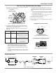
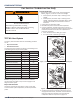
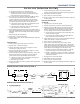
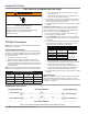
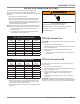
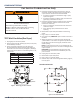
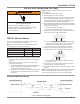
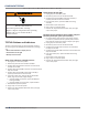
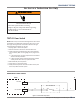
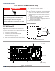
Table Of Contents
- Whirlpool & Maytag 27" Front-Load Gas & Electric Dryers
- Table of Contents
- Section 1: General Information
- Section 2: Diagnostics & Troubleshooting
- Section 3: Component Testing
- Testing - Safety Information
- Component Locations - Whirlpool
- Wiring Diagram - Whirlpool Electric
- Wiring Diagram - Whirlpool Gas
- Wiring Diagram - Maytag Electric
- Wiring Diagram - Maytag Gas
- Component Testing
- TEST #1: ACU Power Check
- TEST #2: Supply Connections
- TEST #3: Motor Circuit
- TEST #4: Heat System
- TEST #4a: Thermistors
- TEST #4b: Thermal Fuse
- TEST #4c: Thermal Cut-Off
- TEST #4d: Gas Valve (Gas Dryer)
- TEST #5: Moisture Sensor
- TEST #6: Buttons & Indicators
- TEST #7: Door Switch
- TEST #8: Drum LED
- TEST #9: Water Valve
- Section 4: Component Access
- Component Locations - Whirlpool
- Door Reversal - Round Shaped Doors
- Door Reversal - Square Shaped Doors
- Removing the Top Panel & Console/HMI
- Removing the Appliance Control Unit (ACU)
- Removing the Front Panel & Door Switch
- Removing the Drum Light & Moisture Sensor
- Removing the Belt, Drum, and Rollers
- Removing the Drive Motor
- Removing the Thermal Fuse & Outlet Thermistor
- Removing the Heater, High Limit Thermostat & Thermal Cutoff
- Removing the Ignitor, Flame Sensor, High-Limit Thermostat and Thermal Cutoff (Gas Models)
- Removing the Gas Burner Assembly Coils (Gas Models)
- Removing the Rear Panel
- Removing the Water Valve
- Section 5: Connectivity
- Product Specifications & Warranty Info

COMPONENT TESTING
Whirlpool & Maytag Front-Load Dryers
n
3-13
For Service Technician Use Only
9. Remove the bare copper wire terminal from pin 5 of black
drive motor switch. See gure 3.
3$*(
FOR SERVICE TECHNICIAN’S USE ONLY
DO NOT REMOVE OR DESTROY
1
5
3
4
6
2
Figure 6 - Remove white connector.
White
Connector
Drive Motor
Switch
8. Remove the white connector from the drive
motor switch. See figure 6.
9. Remove the bare copper wire terminal from
pin 5 of black drive motor switch. See figure 7.
10. Using figure 7 and the strip circuit on
page 20, check for the resistance values of
the motor’s Main and Start winding coils as
shown in the following table.
NOTE: Main and Start winding coils must be
checked at the motor.
1
5
3
4
6
2
Main Winding:
Lt. Blue Wire in Back
and Bare Copper Wire
Start
Winding:
Lt. Blue Wire
in Back and
Bare Copper
Wire
Figure 7 - Main and start winding measure points.
Winding
Resistance
in ohms
Contact Points
of Measurement
MAIN 3.3–3.6
Lt. blue wire in back at pin 4
and bare copper wire terminal
removed from pin 5 of black
drive motor switch
START 2.7–3.0
Lt. blue wire in back at pin 4
and bare copper wire terminal
on pin 3 of black drive
motor switch
¾If the resistance at the motor is correct,
there is an open circuit between the motor
and CCU.
¾If the Main or Start winding resistance is
much greater or less than the values listed
in the table above, replace the motor.
11. Reassemble all parts and panels.
12. Plug in dryer or reconnect power.
13. Perform steps under “Install Diagnostics”,
page 6, to verify repair.
TEST #4: Heat System
This test is performed when either of the
following situations occurs:
✓Dryer does not heat
✓Heat will not shut off
This test checks the components making up
the heating circuit. The following items are
part of this system:
Part of Heating System
Electric
Dryer
Harness/connection
ü
Heater relay
ü
Heat element assembly
ü
Centrifugal switch
ü
Outlet thermistor
ü
Compressor thermistor
ü
Machine control electronics
ü
Console electronics and housing
assembly
ü
Figure 3 - Main and start winding measure points
10. Using gure 3 and the strip circuit below, check for the
resistance values of the motor’s Main and Start winding
coils as shown in the following table.
NOTE: Main and Start winding coils must be checked at
the motor.
Winding Resistance
in ohms
Contact Points
of Measurements
MAIN 3.3–3.6 Blue wire in back at pin 4
and bare copper wire terminal
removed from pin 5 of black
drive motor switch
START 2.7–3.0 Blue wire in back at pin 4
and bare copper wire terminal
on pin 3 of black drive
motor switch
¾ If the resistance at the motor is correct, there is an
open circuit between the motor and ACU. For gas
models, check for a belt switch problem; see step 11.
For electric models, check and repair the main wiring
harness.
¾ If the Main or Start winding resistance is much greater
or less than the values listed in the table above, replace
the motor.
11. On gas dryer only: check the belt switch by measuring
resistance between the two light blue wires in the belt
switch connector block while pushing up the belt switch
pulley.
¾ If the resistance reading goes from open to a few ohms
as pulley arm closes the switch, belt switch is good. If
not, replace the belt switch.
¾ If belt switch is good and there is sll an open circuit,
check and repair the main wiring harness.
12. Reassemble all parts and panels.
13. Plug in dryer or reconnect power.
14. Perform steps under “Service DIagnosc Mode”, page 2-4,
to verify repair.
Pluggable Drive Motor Switch
3$*(
FOR SERVICE TECHNICIAN’S USE ONLY
DO NOT REMOVE OR DESTROY
1M 2M 3M 5M 6M
=
Contacts
Function
Start
Run
Contacts closed
Black
Light Blue
Light Blue
White
White
Centrifugal Switch (Motor)
Gas Valve, Gas Dryer Pluggable Drive Motor Switch
COMPONENT LOCATIONS
• ACU
• User Interface (UI)
• Inlet Thermistor (Gas)
• Water Nozzle
• Water Valve
• Thermal Cut-off
• Inlet Thermistor (Electric)
• High Limit Thermostat
• Heater Assembly
Drum Light
Assembly
Door Switch
(Location may vary
between models)
• Motor Assembly
• Thermal Fuse
• Outlet Thermistor
• Moisture Sensor Strips
Figure 16 - Component locations.
NOTE: Refer to Figure 10b, page 17,
for gas dryer component locations.
Red
Lt. Blue White
Green-Yellow
Red-White
Lt. Blue
Figure 4 - Pluggable Drive Motor Switch
Centrifugal Switch (Motor) Contacts
3$*(
FOR SERVICE TECHNICIAN’S USE ONLY
DO NOT REMOVE OR DESTROY
1M 2M 3M 5M 6M
=
Contacts
Function
Start
Run
Contacts closed
Light Blue
White
Green-Yellow
GM
Centrifugal Switch (Motor) Pluggable Drive Motor Switch
COMPONENT LOCATIONS
Drum Light
Assembly
Door Switch
Figure 9 - Component locations.
Moisture
Sensor
Strips
Auxiliary
Fan
Cycle Control
Unit (CCU)
User Interface
(UI)
For internal components, see Figure 10, page 22.
Figure 4 - Centrifugal Switch Contacts
MOTOR STRIP CIRCUIT
Figure 7 - Motor Strip Circuit
3$*(
FOR SERVICE TECHNICIAN’S USE ONLY
DO NOT REMOVE OR DESTROY
¾Check that the water valve assembly hose
is connected to the nozzle.
8. If everything is hooked up and the water
still does not dispense:
¾Unplug dryer or disconnect power.
¾Replace the valve assembly and retest.
9. If the preceding steps did not correct
the problem, replace the ACU.
STRIP CIRCUITS
MOTOR CIRCUIT
HEATER (ELECTRIC)
HEATER (GAS)
THERMISTORS (INLET/OUTLET)
MOISTURE SENSOR
WATER VALVE CIRCUIT (on some models)
L1
BK
J9-2
APPLIANCE CONTROL UNIT
J9-1
K1
MOTOR RELAY
LBU
(ELECT. ONLY)
THERMAL
FUSE
LBU
(GAS ONLY)
BROKEN
BELT
SWITCH
LBU
4M
JUMPER
LBU
MAIN
START
2.7-3.0 Ω
3.3-3.6 Ω
3M
5M
6M
2M
1M
See Heater Circuit
BU
N.O.
W
LBU
N
CENTRIFUGAL
SWITCH
DOOR
SWITCH
DRIVE MOTOR
1/3 HP
L1
APPLIANCE CONTROL UNIT
BK
K2
HEATER RELAY 1
N.O.
50-500 Ω
HIGH LIMIT
THERMOSTAT
CENTRIFUGAL SWITCH
1M
2M
3M
5M
6M
N
COM1
R
N.C.
BK
THERMAL
CUT-OFF
R-W
BU
THERMAL
FUSE
MOV
BK
LBU
FS1
FS2
45
1
3
2
1V
IG
IGR
HEATER GAS VALVE
1400 ± 70 Ω
570 ± 28.5 Ω
1300 ± 65 Ω
W
W
W
FLAME
SENSOR
VALVE 1
VALVE 2
IGNITOR
R
LBUBU
See
Motor
Circuit
BU
W
DOOR
SWITCH
APPLIANCE CONTROL UNIT
J14-2
50K Ω
R
J14-3
R-W
R
R-W
10K Ω
INLET TEMP THERMISTOR
OUTLET TEMP THERMISTOR
J14-1
J14-6
INLET THERMISTOR
OUTLET THERMISTOR
APPLIANCE CONTROL UNIT
INLET THERMISTOR RTN
OUTLET THERMISTOR RTN
APPLIANCE CONTROL UNIT
J13-1
Y-R
MOISTURE SENSOR
APPLIANCE CONTROL UNIT
MOISTURE SENSOR RTN
MOISTURE SENSOR
J13-2
J8-2
CHASSIS GND
Y-R
MOV MOV
YY
G-YG-Y
G-Y
CHASSIS GND
L1
N
WATER VALVE
J8-1
K4
VALVE RELAY
510-590 Ω
BK R
APPLIANCE CONTROL UNIT
J8-3
W
Figure 14 - Strip circuits.
L1
BK
N.O.
APPLIANCE CONTROL UNIT
COM1
HEATER RELAY 1
R
V R-W
HEATER
R-W
3M
5M
6M
2M
1M
See
Motor
Circuit
R
L2
CENTRIFUGAL SWITCH
K2
THERMAL
CUT-OFF
HIGH LIMIT
THERMOSTAT
N.C.
THERMAL
FUSE