
Service Manual
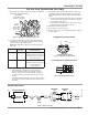
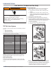
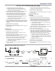
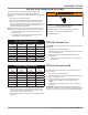
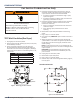
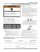
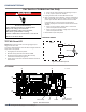
Table Of Contents
- Whirlpool & Maytag 27" Front-Load Gas & Electric Dryers
- Table of Contents
- Section 1: General Information
- Section 2: Diagnostics & Troubleshooting
- Section 3: Component Testing
- Testing - Safety Information
- Component Locations - Whirlpool
- Wiring Diagram - Whirlpool Electric
- Wiring Diagram - Whirlpool Gas
- Wiring Diagram - Maytag Electric
- Wiring Diagram - Maytag Gas
- Component Testing
- TEST #1: ACU Power Check
- TEST #2: Supply Connections
- TEST #3: Motor Circuit
- TEST #4: Heat System
- TEST #4a: Thermistors
- TEST #4b: Thermal Fuse
- TEST #4c: Thermal Cut-Off
- TEST #4d: Gas Valve (Gas Dryer)
- TEST #5: Moisture Sensor
- TEST #6: Buttons & Indicators
- TEST #7: Door Switch
- TEST #8: Drum LED
- TEST #9: Water Valve
- Section 4: Component Access
- Component Locations - Whirlpool
- Door Reversal - Round Shaped Doors
- Door Reversal - Square Shaped Doors
- Removing the Top Panel & Console/HMI
- Removing the Appliance Control Unit (ACU)
- Removing the Front Panel & Door Switch
- Removing the Drum Light & Moisture Sensor
- Removing the Belt, Drum, and Rollers
- Removing the Drive Motor
- Removing the Thermal Fuse & Outlet Thermistor
- Removing the Heater, High Limit Thermostat & Thermal Cutoff
- Removing the Ignitor, Flame Sensor, High-Limit Thermostat and Thermal Cutoff (Gas Models)
- Removing the Gas Burner Assembly Coils (Gas Models)
- Removing the Rear Panel
- Removing the Water Valve
- Section 5: Connectivity
- Product Specifications & Warranty Info

COMPONENT TESTING
Whirlpool & Maytag Front-Load Dryers
n
3-17
The ACU monitors the inlet temperature using the inlet
thermistor. The inlet thermistor (along with the outlet
thermistor) is used to detect air ow, and assists in calculang
load size.
1. Unplug dryer or disconnect power.
2. Remove the top panel to access the machine electronics.
3. Remove connector J14 from the ACU and measure the
resistance between J14-1 and J14-2 at the connector. The
following tables (electric & gas) give temperatures and
their associated resistance values.
NOTE: All thermistor resistance measurements must be made
while dryer is unplugged and connector removed from ACU.
¾ If the resistance is OK, the inlet thermistor is good.
Proceed to step 4.
¾ If the thermistor resistance does not agree with the
table, replace the inlet thermistor.
ELECT - INLET THERMISTOR RESISTANCE
TEMP
°F (°C)
RES. RANGE
k ohms
TEMP
°F (°C)
RES. RANGE
k ohms
68° (20°) 61.2–63.7 131° (55°) 14.5–15.3
77° (25°) 49.0–51.0 140° (60°) 12.1–12.8
86° (30°) 39.5–41.1 149° (65°) 10.2–10.7
95° (35°) 32.0–33.3 158° (70°) 8.5–9.0
104° (40°) 26.1–27.2 167° (75°) 7.2–7.6
113° (45°) 21.4–22.3 176° (80°) 6.1–6.5
122° (50°) 17.6–18.5
GAS - INLET THERMISTOR RESISTANCE
TEMP
°F (°C)
RES. RANGE
k ohms
TEMP
°F (°C)
RES. RANGE
k ohms
68° (20°) 57.5–67.6 131° (55°) 14.1–15.6
77° (25°) 46.1–53.8 140° (60°) 11.8–12.9
86° (30°) 37.4–43.1 149° (65°) 9.9–10.8
95° (35°) 30.4–34.7 158° (70°) 8.4–9.0
104° (40°) 24.9–28.2 167° (75°) 7.1–7.6
113° (45°) 20.5–23.0 176° (80°) 6.0–6.4
122° (50°) 16.9–18.9
4. Check J14-1 and J14-2 to dryer cabinet ground. If either
pin indicates connuity to ground (short), replace wiring
harness; otherwise, proceed to step 5.
5. If the preceding steps did not correct the problem, replace
the ACU.
For Service Technician Use Only
TEST #4b: Thermal Fuse
ALL DRYERS: The thermal fuse is wired in series with the dryer
drive motor.
1. Unplug dryer or disconnect power.
2. Remove top panel, front panel and bulkhead, and drum to
access the thermal fuse.
3. Using an ohmmeter, check the connuity across the
thermal fuse.
¾ If the ohmmeter indicates an open circuit, replace the
thermal fuse.
TEST #4c: Thermal Cut-O
If the dryer does not produce heat, check the status of the
thermal cut-o.
1. Unplug dryer or disconnect power.
2. Remove top panel, front panel and bulkhead, and drum to
access the thermal cut-o.
3. Using an ohmmeter, check the connuity across the
thermal cut-o. See gures 1 and 2, page 3-14, for
locaon.
4. If the ohmmeter indicates an open circuit, perform the
following:
ALL DRYERS: Replace both the thermal cut-o and high limit
thermostat. In addion, check for blocked or improper exhaust
system, and, on electric dryers, for heat element malfuncon.
WARNING
Electrical Shock Hazard
Disconnect power before servicing.
Failure to do so can result in death or
electrical shock.
Replace all parts and panels before operating.