
Service Manual
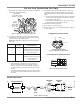
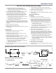
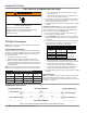
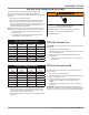
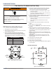
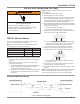
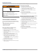
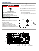
Table Of Contents
- Whirlpool & Maytag 27" Front-Load Gas & Electric Dryers
- Table of Contents
- Section 1: General Information
- Section 2: Diagnostics & Troubleshooting
- Section 3: Component Testing
- Testing - Safety Information
- Component Locations - Whirlpool
- Wiring Diagram - Whirlpool Electric
- Wiring Diagram - Whirlpool Gas
- Wiring Diagram - Maytag Electric
- Wiring Diagram - Maytag Gas
- Component Testing
- TEST #1: ACU Power Check
- TEST #2: Supply Connections
- TEST #3: Motor Circuit
- TEST #4: Heat System
- TEST #4a: Thermistors
- TEST #4b: Thermal Fuse
- TEST #4c: Thermal Cut-Off
- TEST #4d: Gas Valve (Gas Dryer)
- TEST #5: Moisture Sensor
- TEST #6: Buttons & Indicators
- TEST #7: Door Switch
- TEST #8: Drum LED
- TEST #9: Water Valve
- Section 4: Component Access
- Component Locations - Whirlpool
- Door Reversal - Round Shaped Doors
- Door Reversal - Square Shaped Doors
- Removing the Top Panel & Console/HMI
- Removing the Appliance Control Unit (ACU)
- Removing the Front Panel & Door Switch
- Removing the Drum Light & Moisture Sensor
- Removing the Belt, Drum, and Rollers
- Removing the Drive Motor
- Removing the Thermal Fuse & Outlet Thermistor
- Removing the Heater, High Limit Thermostat & Thermal Cutoff
- Removing the Ignitor, Flame Sensor, High-Limit Thermostat and Thermal Cutoff (Gas Models)
- Removing the Gas Burner Assembly Coils (Gas Models)
- Removing the Rear Panel
- Removing the Water Valve
- Section 5: Connectivity
- Product Specifications & Warranty Info

3-18
n
Whirlpool & Maytag Front-Load Dryers
COMPONENT TESTING
TEST #4d: Gas Valve (Gas Dryer)
1. Unplug dryer or disconnect power.
2. Access the gas valve by removing top panel, front panel,
front bulkhead, and drum.
3. Use an ohmmeter to determine if a gas valve coil
has malfunconed. Remove harness plugs. Measure
resistance across the terminals (see gure 1). Readings
should match those shown in the following chart; if not,
replace coils.
GAS VALVE RESISTANCE
Terminals Resistance in ohms
1 to 2 1400 ± 70
1 to 3 570 ± 28.5
4 to 5 1300 ± 65
3$*(
FOR SERVICE TECHNICIAN’S USE ONLY
DO NOT REMOVE OR DESTROY
4. Check J14-1 and J14-2 to dryer cabinet
ground. If either pin indicates continuity
to ground (short), replace wiring harness;
otherwise, proceed to step 5.
5. If the preceding steps did not correct the
problem, replace the ACU.
TEST #4b: Thermal Fuse
ALL DRYERS: The thermal fuse is wired
in series with the dryer drive motor.
1. Unplug dryer or disconnect power.
2. Slide the top back, remove the front panel,
front bulkhead, and drum to access the
thermal fuse.
3. Using an ohmmeter, check the continuity
across the thermal fuse.
¾If the ohmmeter indicates an open circuit,
replace the thermal fuse.
TEST #4c: Thermal Cut-Off
If the dryer does not produce heat, check the
status of the thermal cut-off.
1. Unplug dryer or disconnect power.
2. Access the thermal cut-off by removing
console, top panel, front panel, front
bulkhead, and drum.
3. Using an ohmmeter, check the continuity
across the thermal cut-off. See figures 10a
and 10b, page 17, for location.
4. If the ohmmeter indicates an open circuit,
perform the following:
ALL DRYERS: Replace both the thermal
cut-off and high limit thermostat. In addition,
check for blocked or improper exhaust
system, and, on electric dryers, for heat
element malfunction.
TEST #4d: Gas Valve (Gas Dryer)
1. Unplug dryer or disconnect power.
2. Access the gas valve by sliding the top
back and removing the front panel, front
bulkhead, and drum.
3. Use an ohmmeter to determine if a
gas valve coil has malfunctioned. Remove
harness plugs. Measure resistance across
the terminals (see figure 11). Readings should
match those shown in the following chart;
if not, replace coils.
4. Disconnect the ignitor plug from the
burner. Using an ohmmeter, measure
the resistance across the ignitor’s 2-pin
connector. Resistance should be 50-500 1.
¾If resistance readings are outside the range
or open, replace the ignitor.
¾If resistance readings are within range,
reconnect the ignitor plug and continue
to step 5.
5. Disconnect the wires going to the flame
sensor terminals. Using an ohmmeter, measure
across the two sensor terminals for continuity.
¾If there is continuity, reconnect the sensor
wires and continue to step 6.
¾If the reading is open, the flame sensor
needs replacing.
6. Reassemble all parts and panels before
reconnecting power.
7. Plug in dryer or reconnect power.
8. Run a high-temp MIXED + TIMED DRY
cycle of at least 2 minutes in duration.
9. Watch the ignitor for a couple of minutes
through the “peek window” in the side. If the
ignitor stays red hot and the gas does not come
out and ignite, the flame sensor needs replacing.
NOTE: If ignitor does not come on, line voltage
may not be present at the gas burner. The motor
centrifugal switch may be suspect.
Black
Light Blue
White
Figure 11 - Measuring gas valve resistance.
Terminals
Resistance
in ohms
1 to 2 1400 ± 70
1 to 3 570 ± 28.5
4 to 5 1300 ± 65
GAS VALVE RESISTANCE
White
Light Blue
Figure 1 - Measuring gas valve resistance.
For Service Technician Use Only
4. Disconnect the ignitor plug from the burner. Using an
ohmmeter, measure the resistance across the ignitor’s
2-pin connector. Resistance should be 50-500 Ω.
¾ If resistance readings are outside the range or open,
replace the ignitor.
¾ If resistance readings are within range, reconnect the
ignitor plug and connue to step 5.
5. Disconnect the wires going to the ame sensor terminals.
Using an ohmmeter, measure across the two sensor
terminals for connuity.
¾ If there is connuity, reconnect the sensor wires and
connue to step 6.
¾ If the reading is open, the ame sensor needs
replacing.
6. Reassemble all parts and panels before reconnecng
power.
7. Plug in dryer or reconnect power.
8. Run a high-temp TIMED DRY cycle of at least 2 minutes in
duraon.
9. Watch the ignitor for a couple of minutes through the
“peek window” in the side. If the ignitor stays red hot and
the gas does not come out and ignite, the ame sensor
needs replacing.
NOTE: If ignitor does not come on, line voltage may not
be present at the gas burner. The motor centrifugal switch
may be suspect.
IMPORTANT: To avoid damage to the gas burner wire
harness, ensure the harness is routed exactly as it was
prior to service.
10. Unplug dryer or disconnect power.
11. Reassemble all parts and panels.
12. Plug in dryer or reconnect power.
13. Perform steps under “Service Diagnosc Mode”, page 2-4,
to verify repair.
Gas Valve Schematic
WARNING
Electrical Shock Hazard
Disconnect power before servicing.
Failure to do so can result in death or
electrical shock.
Replace all parts and panels before operating.
Figure 2 - Gas Valve Schematic
3$*(
FOR SERVICE TECHNICIAN’S USE ONLY
DO NOT REMOVE OR DESTROY
IMPORTANT: Electrostatic discharge may cause damage to machine control electronics. See page 1 for ESD information.
GAS DRYER WIRING DIAGRAM
Figure 15 - Wiring Diagram, Gas
50-500 Ω
570 ± 28.5 Ω1400 ± 70 Ω
1300 ± 65 Ω
1
2
3
4
5