
Service Manual
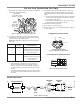
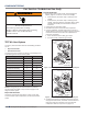
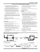
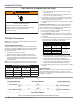
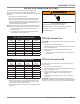
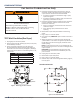
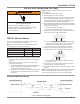
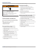
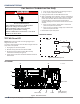
Table Of Contents
- Whirlpool & Maytag 27" Front-Load Gas & Electric Dryers
- Table of Contents
- Section 1: General Information
- Section 2: Diagnostics & Troubleshooting
- Section 3: Component Testing
- Testing - Safety Information
- Component Locations - Whirlpool
- Wiring Diagram - Whirlpool Electric
- Wiring Diagram - Whirlpool Gas
- Wiring Diagram - Maytag Electric
- Wiring Diagram - Maytag Gas
- Component Testing
- TEST #1: ACU Power Check
- TEST #2: Supply Connections
- TEST #3: Motor Circuit
- TEST #4: Heat System
- TEST #4a: Thermistors
- TEST #4b: Thermal Fuse
- TEST #4c: Thermal Cut-Off
- TEST #4d: Gas Valve (Gas Dryer)
- TEST #5: Moisture Sensor
- TEST #6: Buttons & Indicators
- TEST #7: Door Switch
- TEST #8: Drum LED
- TEST #9: Water Valve
- Section 4: Component Access
- Component Locations - Whirlpool
- Door Reversal - Round Shaped Doors
- Door Reversal - Square Shaped Doors
- Removing the Top Panel & Console/HMI
- Removing the Appliance Control Unit (ACU)
- Removing the Front Panel & Door Switch
- Removing the Drum Light & Moisture Sensor
- Removing the Belt, Drum, and Rollers
- Removing the Drive Motor
- Removing the Thermal Fuse & Outlet Thermistor
- Removing the Heater, High Limit Thermostat & Thermal Cutoff
- Removing the Ignitor, Flame Sensor, High-Limit Thermostat and Thermal Cutoff (Gas Models)
- Removing the Gas Burner Assembly Coils (Gas Models)
- Removing the Rear Panel
- Removing the Water Valve
- Section 5: Connectivity
- Product Specifications & Warranty Info

COMPONENT TESTING
Whirlpool & Maytag Front-Load Dryers
n
3-19
For Service Technician Use Only
TEST #5: Moisture Sensor
This test is performed when an automac cycle stops too
soon, or runs much longer than expected.
NOTE: Dryer will shut down automacally aer 2½ hours.
The following items are part of this system:
Part of Moisture System Electric Dryer Gas
Harness/connecon
ü ü
Metal sensor strips
ü ü
ACU
ü ü
NOTE: Refer to strip circuit below to diagnose moisture sensor.
1. Acvate the Service Diagnosc Mode. See procedures on
page 2-4.
2. Open the door. Using a wet cloth or one nger, jointly
touch both sensor strips.
¾ If a repeang beep tone is heard and an alphanumeric
number is displayed on the console, the moisture
sensor passes the test. Go to step 9.
¾ If a beep tone is not heard, or a repeang beep tone is
heard before touching both moisture strips, connue
with step 3.
NOTE: Overdrying may be caused by a short circuit in the
sensor system.
3. Unplug dryer or disconnect power.
4. Remove top panel to access the ACU.
5. Access the moisture sensor wires by removing the console
and front panel (see pages 4-9 & 4-11). Disconnect the
3-wire moisture sensor connector located below the door
opening between the front panel and bulkhead.
6. Access the ACU and remove connector J13 from the ACU.
Check the wire harness for connuity between J13 and the
moisture sensor connector.
¾ If there is connuity, go to step 7.
¾ If there is no connuity, replace the main harness.
7. Measure the resistance across the outermost contacts of
the connector that includes the two MOVs.
3$*(
FOR SERVICE TECHNICIAN’S USE ONLY
DO NOT REMOVE OR DESTROY
TEST #5: Moisture Sensor
This test is performed when an automatic
cycle stops too soon, or runs much longer
than expected.
NOTE: Dryer will shut down automatically
after 4 hours and 10 minutes.
The following items are part of this system:
NOTE: Refer to strip circuit on page 20
to diagnose moisture sensor.
1. Activate the Loads Test mode. See
procedures on page 4.
2. Open the door. Using a wet cloth or one
finger, jointly touch both sensor strips.
¾If a repeating beep tone is heard and an
alphanumeric number is displayed on the
console, the moisture sensor passes the
test. Go to step 9.
¾If a beep tone is not heard, or a repeating
beep tone is heard before touching both
moisture strips, continue with step 3.
NOTE: Overdrying may be caused by a short
circuit in the sensor system.
3. Unplug dryer or disconnect power.
4. Remove top panel to access the machine
electronics.
5. Access the moisture sensor wires
by removing the console and front panel.
Disconnect the 3-wire moisture sensor
connector located below the door opening
between the front panel and bulkhead.
6. Access the CCU and remove connector
P13 from the circuit board. Check the wire
harness for continuity between P13 and the
moisture sensor connector.
¾If there is continuity, go to step 7.
¾If there is no continuity, replace the main
harness.
Part of Moisture System
Electric
Dryer
Harness/connection
ü
Metal sensor strips
ü
Machine control electronics
ü
7. Measure the resistance across the
outermost contacts of the connector that
includes the two MOVs.
¾If a small resistance is measured, clean the
two metal moisture strips inside the drum.
If a small resistance is measured after
cleaning, replace sensor harness.
¾If a small resistance is not measured,
go to step 8.
8. Measure the resistance across each of the
outermost contacts and the center terminal
(ground connection).
¾If a resistance less than infinity is
measured, replace the sensor harness.
9. If the moisture sensor diagnostic test passes,
check the outlet thermistor: TEST #4a, page 15.
¾If the problem persists after replacing the
moisture sensor and thermistor, consider
adjusting the dryness level (see TEST #5a:
Adjusting Customer-Focused Dryness Level).
10. If the preceding steps did not correct the
problem, replace the CCU.
TEST #5a: Adjusting Customer-
Focused Dryness Level
NOTE: If the customer complains about the
clothes being less dry or more dry than desired
and the moisture sensor passes TEST #5:
Moisture Sensor, step 2, the total dry time can
be lengthened or shortened by changing the
Customer-Focused Dryness Level from “1”
(standard auto cycle) to a “2” (15% more drying
time), “3” (30% more drying time), “4” (15%
less drying time), or “5” (30% less drying time)
auto cycle.
1. In standby mode (dryer plugged in but not
powered up), press and hold the DRYNESS
LEVEL button for approximately 3 seconds.
The dryer will beep and “CF” is displayed
followed by the current dryness setting on the
7-segment display. The factory default value
is “1”.
¾ If a small resistance is measured, clean the two metal
moisture strips inside the drum. If a small resistance is
measured aer cleaning, replace sensor harness.
¾ If a small resistance is not measured, go to step 8.
8. Measure the resistance across each of the outermost
contacts and the center terminal (ground connecon).
3$*(
FOR SERVICE TECHNICIAN’S USE ONLY
DO NOT REMOVE OR DESTROY
TEST #5: Moisture Sensor
This test is performed when an automatic
cycle stops too soon, or runs much longer
than expected.
NOTE: Dryer will shut down automatically
after 4 hours and 10 minutes.
The following items are part of this system:
NOTE: Refer to strip circuit on page 20
to diagnose moisture sensor.
1. Activate the Loads Test mode. See
procedures on page 4.
2. Open the door. Using a wet cloth or one
finger, jointly touch both sensor strips.
¾If a repeating beep tone is heard and an
alphanumeric number is displayed on the
console, the moisture sensor passes the
test. Go to step 9.
¾If a beep tone is not heard, or a repeating
beep tone is heard before touching both
moisture strips, continue with step 3.
NOTE: Overdrying may be caused by a short
circuit in the sensor system.
3. Unplug dryer or disconnect power.
4. Remove top panel to access the machine
electronics.
5. Access the moisture sensor wires
by removing the console and front panel.
Disconnect the 3-wire moisture sensor
connector located below the door opening
between the front panel and bulkhead.
6. Access the CCU and remove connector
P13 from the circuit board. Check the wire
harness for continuity between P13 and the
moisture sensor connector.
¾If there is continuity, go to step 7.
¾If there is no continuity, replace the main
harness.
Part of Moisture System
Electric
Dryer
Harness/connection
ü
Metal sensor strips
ü
Machine control electronics
ü
7. Measure the resistance across the
outermost contacts of the connector that
includes the two MOVs.
¾If a small resistance is measured, clean the
two metal moisture strips inside the drum.
If a small resistance is measured after
cleaning, replace sensor harness.
¾If a small resistance is not measured,
go to step 8.
8. Measure the resistance across each of the
outermost contacts and the center terminal
(ground connection).
¾If a resistance less than infinity is
measured, replace the sensor harness.
9. If the moisture sensor diagnostic test passes,
check the outlet thermistor: TEST #4a, page 15.
¾If the problem persists after replacing the
moisture sensor and thermistor, consider
adjusting the dryness level (see TEST #5a:
Adjusting Customer-Focused Dryness Level).
10. If the preceding steps did not correct the
problem, replace the CCU.
TEST #5a: Adjusting Customer-
Focused Dryness Level
NOTE: If the customer complains about the
clothes being less dry or more dry than desired
and the moisture sensor passes TEST #5:
Moisture Sensor, step 2, the total dry time can
be lengthened or shortened by changing the
Customer-Focused Dryness Level from “1”
(standard auto cycle) to a “2” (15% more drying
time), “3” (30% more drying time), “4” (15%
less drying time), or “5” (30% less drying time)
auto cycle.
1. In standby mode (dryer plugged in but not
powered up), press and hold the DRYNESS
LEVEL button for approximately 3 seconds.
The dryer will beep and “CF” is displayed
followed by the current dryness setting on the
7-segment display. The factory default value
is “1”.
¾ If a resistance less than innity is measured, replace
the sensor harness.
9. If the moisture sensor diagnosc test passes, check the
outlet thermistor: TEST #4a, page 3-16.
10. If the preceding steps did not correct the problem, replace
the ACU.
NOTE: Some Maytag models have an addional set of moisture
sensors located at the back of the drum. To test the rear
moisture sensor, repeat steps 6-10, using connector J23.
WARNING
Electrical Shock Hazard
Disconnect power before servicing.
Failure to do so can result in death or
electrical shock.
Replace all parts and panels before operating.
MOISTURE SENSOR STRIP CIRCUIT
Figure 1 - Moisture Sensor Strip Circuit
3$*(
FOR SERVICE TECHNICIAN’S USE ONLY
DO NOT REMOVE OR DESTROY
¾Check that the water valve assembly hose
is connected to the nozzle.
8. If everything is hooked up and the water
still does not dispense:
¾Unplug dryer or disconnect power.
¾Replace the valve assembly and retest.
9. If the preceding steps did not correct
the problem, replace the ACU.
STRIP CIRCUITS
MOTOR CIRCUIT
HEATER (ELECTRIC)
HEATER (GAS)
THERMISTORS (INLET/OUTLET)
MOISTURE SENSOR
WATER VALVE CIRCUIT (on some models)
L1
BK
J9-2
APPLIANCE CONTROL UNIT
J9-1
K1
MOTOR RELAY
LBU
(ELECT. ONLY)
THERMAL
FUSE
LBU
(GAS ONLY)
BROKEN
BELT
SWITCH
LBU
4M
JUMPER
LBU
MAIN
START
2.7-3.0 Ω
3.3-3.6 Ω
3M
5M
6M
2M
1M
See Heater Circuit
BU
N.O.
W
LBU
N
CENTRIFUGAL
SWITCH
DOOR
SWITCH
DRIVE MOTOR
1/3 HP
L1
APPLIANCE CONTROL UNIT
BK
K2
HEATER RELAY 1
N.O.
50-500 Ω
HIGH LIMIT
THERMOSTAT
CENTRIFUGAL SWITCH
1M
2M
3M
5M
6M
N
COM1
R
N.C.
BK
THERMAL
CUT-OFF
R-W
BU
THERMAL
FUSE
MOV
BK
LBU
FS1
FS2
45
1
3
2
1V
IG
IGR
HEATER GAS VALVE
1400 ± 70 Ω
570 ± 28.5 Ω
1300 ± 65 Ω
W
W
W
FLAME
SENSOR
VALVE 1
VALVE 2
IGNITOR
R
LBUBU
See
Motor
Circuit
BU
W
DOOR
SWITCH
APPLIANCE CONTROL UNIT
J14-2
50K Ω
R
J14-3
R-W
R
R-W
10K Ω
INLET TEMP THERMISTOR
OUTLET TEMP THERMISTOR
J14-1
J14-6
INLET THERMISTOR
OUTLET THERMISTOR
APPLIANCE CONTROL UNIT
INLET THERMISTOR RTN
OUTLET THERMISTOR RTN
APPLIANCE CONTROL UNIT
J13-1
Y-R
MOISTURE SENSOR
APPLIANCE CONTROL UNIT
MOISTURE SENSOR RTN
MOISTURE SENSOR
J13-2
J8-2
CHASSIS GND
Y-R
MOV MOV
YY
G-YG-Y
G-Y
CHASSIS GND
L1
N
WATER VALVE
J8-1
K4
VALVE RELAY
510-590 Ω
BK R
APPLIANCE CONTROL UNIT
J8-3
W
Figure 14 - Strip circuits.
L1
BK
N.O.
APPLIANCE CONTROL UNIT
COM1
HEATER RELAY 1
R
V R-W
HEATER
R-W
3M
5M
6M
2M
1M
See
Motor
Circuit
R
L2
CENTRIFUGAL SWITCH
K2
THERMAL
CUT-OFF
HIGH LIMIT
THERMOSTAT
N.C.