
Service Manual
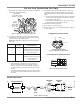
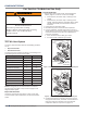
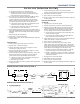
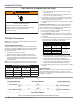
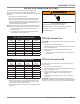
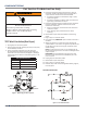
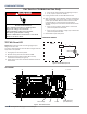
Table Of Contents
- Whirlpool & Maytag 27" Front-Load Gas & Electric Dryers
- Table of Contents
- Section 1: General Information
- Section 2: Diagnostics & Troubleshooting
- Section 3: Component Testing
- Testing - Safety Information
- Component Locations - Whirlpool
- Wiring Diagram - Whirlpool Electric
- Wiring Diagram - Whirlpool Gas
- Wiring Diagram - Maytag Electric
- Wiring Diagram - Maytag Gas
- Component Testing
- TEST #1: ACU Power Check
- TEST #2: Supply Connections
- TEST #3: Motor Circuit
- TEST #4: Heat System
- TEST #4a: Thermistors
- TEST #4b: Thermal Fuse
- TEST #4c: Thermal Cut-Off
- TEST #4d: Gas Valve (Gas Dryer)
- TEST #5: Moisture Sensor
- TEST #6: Buttons & Indicators
- TEST #7: Door Switch
- TEST #8: Drum LED
- TEST #9: Water Valve
- Section 4: Component Access
- Component Locations - Whirlpool
- Door Reversal - Round Shaped Doors
- Door Reversal - Square Shaped Doors
- Removing the Top Panel & Console/HMI
- Removing the Appliance Control Unit (ACU)
- Removing the Front Panel & Door Switch
- Removing the Drum Light & Moisture Sensor
- Removing the Belt, Drum, and Rollers
- Removing the Drive Motor
- Removing the Thermal Fuse & Outlet Thermistor
- Removing the Heater, High Limit Thermostat & Thermal Cutoff
- Removing the Ignitor, Flame Sensor, High-Limit Thermostat and Thermal Cutoff (Gas Models)
- Removing the Gas Burner Assembly Coils (Gas Models)
- Removing the Rear Panel
- Removing the Water Valve
- Section 5: Connectivity
- Product Specifications & Warranty Info

3-20
n
Whirlpool & Maytag Front-Load Dryers
COMPONENT TESTING
For Service Technician Use Only
TEST #6: Buons and Indicators
This test is performed when any of the following situaons
occurs during the “Key Acvaon & Encoder Test” (see page
2-5).
ü None of the indicators or display turn on
ü Some buons do not light
ü No beep sound is heard
None of the indicators or display turn on:
1. Unplug dryer or disconnect power.
2. Remove top panel to access the ACU and HMI.
3. Visually check that ALL ACU connectors are inserted all
the way into the ACU.
4. Visually check that ALL HMI connectors are inserted all the
way into the HMI.
5. Visually check that the HMI and housing assembly is
properly inserted into the front console.
6. If all visual checks pass, perform TEST #1: ACU Power
Check, page 3-8, to verify supply voltages.
¾ If supply voltages are present, replace the HMI and
housing assembly.
¾ If supply voltages are not present, replace the ACU.
7. Reassemble all parts and panels.
8. Plug in dryer or reconnect power.
9. Perform the “Key Acvaon & Encoder Test” (see page
2-5) to verify repair.
Some buttons do not light:
1. Unplug dryer or disconnect power.
2. Remove top panel to access the ACU and HMI.
3. Visually check that the HMI and housing assembly is
properly inserted into the front console.
4. If visual check passes, replace the HMI and housing
assembly.
5. Reassemble all parts and panels.
6. Plug in dryer or reconnect power.
7. Perform the “Key Acvaon & Encoder Test” (see page
2-5) to verify repair.
No beep sound is heard (on some models, only the
Normal cycle beeps upon cycle selection):
1. On some models, verify that the “Cycle Signal” volume
is turned on. (Procedure varies by model; refer to Use &
Care Guide for specic instrucons to adjust cycle signal.)
2. Unplug dryer or disconnect power.
3. Remove top panel to access the ACU and HMI.
4. Visually check that ALL ACU connectors are inserted all
the way into the ACU.
5. Visually check that ALL HMI connectors are inserted all the
way into the HMI.
6. If all visual checks pass, replace the HMI and housing
assembly.
7. Reassemble all parts and panels.
8. Plug in dryer or reconnect power.
9. Perform the “Key Acvaon & Encoder Test” (see page
2-5) to verify repair.
WARNING
Electrical Shock Hazard
Disconnect power before servicing.
Failure to do so can result in death or
electrical shock.
Replace all parts and panels before operating.