
Service Manual
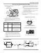
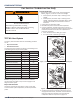
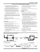
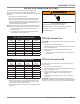
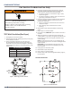
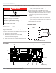
Table Of Contents
- Whirlpool & Maytag 27" Front-Load Gas & Electric Dryers
- Table of Contents
- Section 1: General Information
- Section 2: Diagnostics & Troubleshooting
- Section 3: Component Testing
- Testing - Safety Information
- Component Locations - Whirlpool
- Wiring Diagram - Whirlpool Electric
- Wiring Diagram - Whirlpool Gas
- Wiring Diagram - Maytag Electric
- Wiring Diagram - Maytag Gas
- Component Testing
- TEST #1: ACU Power Check
- TEST #2: Supply Connections
- TEST #3: Motor Circuit
- TEST #4: Heat System
- TEST #4a: Thermistors
- TEST #4b: Thermal Fuse
- TEST #4c: Thermal Cut-Off
- TEST #4d: Gas Valve (Gas Dryer)
- TEST #5: Moisture Sensor
- TEST #6: Buttons & Indicators
- TEST #7: Door Switch
- TEST #8: Drum LED
- TEST #9: Water Valve
- Section 4: Component Access
- Component Locations - Whirlpool
- Door Reversal - Round Shaped Doors
- Door Reversal - Square Shaped Doors
- Removing the Top Panel & Console/HMI
- Removing the Appliance Control Unit (ACU)
- Removing the Front Panel & Door Switch
- Removing the Drum Light & Moisture Sensor
- Removing the Belt, Drum, and Rollers
- Removing the Drive Motor
- Removing the Thermal Fuse & Outlet Thermistor
- Removing the Heater, High Limit Thermostat & Thermal Cutoff
- Removing the Ignitor, Flame Sensor, High-Limit Thermostat and Thermal Cutoff (Gas Models)
- Removing the Gas Burner Assembly Coils (Gas Models)
- Removing the Rear Panel
- Removing the Water Valve
- Section 5: Connectivity
- Product Specifications & Warranty Info

COMPONENT TESTING
Whirlpool & Maytag Front-Load Dryers
n
3-21
For Service Technician Use Only
TEST #7: Door Switch
NOTE: Refer to strip circuit below to diagnose the door switch.
Funconality is veried when opening the door turns on the
drum light. Closing the door should turn o the drum light.
If the preceding condions are not met:
1. Unplug dryer or disconnect power.
2. Remove console to access the machine electronics.
3. Check that the wires between the door switch and ACU
are connected. (Refer to wiring diagrams on pages 3-4 to
3-7.)
¾ If the connecons are good, replace the wire and door
switch assembly and retest.
¾ If wire and door switch assembly have been replaced
and dryer sll does not start, replace the ACU.
4. Reassemble all parts and panels.
5. Plug in dryer or reconnect power.
6. Verify that the dryer will start with the door closed, and
that it stops when the door opens.
WARNING
Electrical Shock Hazard
Disconnect power before servicing.
Failure to do so can result in death or
electrical shock.
Replace all parts and panels before operating.
DOOR SWITCH STRIP CIRCUIT
N
DOOR SWITCH
DOOR SWITCH CIRCUIT
W
ACU
J8-4
W
LBUTBU
W
DOOR SENSE
J8-3
NEUTRAL
W
Figure 1 - Door Switch Strip Circuit