
User Guide


8
Installation Requirements
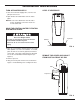
FIG. 7
FIG. 6
3 VALVE BYPASS
Central Water Filtration
System
INLET
INOUT
Clip (2)
Valve
Inlet
1” NPT
Adapter (2)
1” NPT Sweat
Adapter (2)
(not included)
Central Water Filtration
System
OUTLET
CONNECTING PLUMBING TO VALVE
Included
1” NPT
Adapter (2)
Clip (4)
1” NPT Sweat
Adapter (2)
(not included)
Bypass
Valve
Valve
Inlet
INOUT
Included
Use Teflon® tape,
pipe joint com-
pound or both
Use Teflon® tape,
pipe joint com-
pound or both
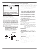
Electrical Shock Hazard
Prior to installation on metallic plumbing,
securely install two grounding clamps and a
#4 copper wire per installation instructions.
Failure to follow these instructions can result
in death or electrical shock.
INLET - OUTLET PLUMBING OPTIONS
Always install either a single bypass valve (provided)
to the contractor/plumber-supplied plumbing, as shown
in Figure 7 OR if desired, a 3 valve bypass system
(parts not included) can be installed, as shown in
Figure 6. Bypass valves allow you to turn off water to
the Central Water Filtration System for maintenance if
needed, but still have water in house pipes.
Use either:
= Copper pipe
= Threaded pipe
= PEX (Crosslinked Polyethylene) pipe
= CPVC plastic pipe
= Other pipe approved for use with potable water
IMPORTANT: Do not solder with plumbing attached to
installation adapters and single valve
bypass. Soldering heat will damage the
adapters and valve.
CROSS OVER
To Central Water
Filtration System
FIG. 5
Main Wat
er
Pi
pe
Treated
Water from
Valve
OUTLET
Untreated
Water to
Valve
INLET
In what direction
does the water flow?
Be sure to plan
piping so water
flow is to the
Central Water
Filtration System
valve INLET.
Plan a crossover
if flow is from left
to right.