How to install, operate and maintain your E-Z Touch Demand Controlled Water Softener Do not return water softener to store If you have any questions or concerns when installing, operating or maintaining your water softener, call our toll free number: 1-866-986-3223 Monday- Friday, 8 AM - 7 PM EST or visit www.ecodynewatertreatment.
TABLE OF CONTENTS Page Specifications & Dimensions . . . . . . . . . . . . . . . . . . . . . . . . . . . . . . . . . . . . . . . . . . . . . . . . . . . . . . . . . . . . . . . . . . . 3 Water Softener Safety . . . . . . . . . . . . . . . . . . . . . . . . . . . . . . . . . . . . . . . . . . . . . . . . . . . . . . . . . . . . . . . . . . . . . . . . 4 Before You Start . . . . . . . . . . . . . . . . . . . . . . . . . . . . . . . . . . . . . . . . . . . . . . . . . . . . . . . . . . . . . . . . . . . . . .
Specifications & Dimensions Model WHES48 Model Code Rated Softening Capacity (Grains @ Salt Dose) Rated Efficiency (Grains/Pound of Salt @ Minimum Salt Dose) Water Used During Regeneration @ Minimum Salt Dose Total Water Used Per Regeneration @ Maximum Salt Dose Rated Service Flow Rate Amount of High Capacity Ion Exchange Resin Pressure Drop at Rated Service Flow Water Supply Max. Hardness Water Supply Max.
Water Softener Safety Your safety and the safety of others are very important. We have provided many safety messages in this manual and on your appliance. Always read and obey all safety messages. This is the safety alert symbol. This symbol alerts you to potential hazards that can kill or hurt you and others.
Inspect Shipment The parts required to assemble and install the water softener are included with the unit. Thoroughly check the water softener for possible shipping damage and parts loss. Also inspect and note any damage to the shipping carton. Remove and discard (or recycle) all packing materials. To avoid loss of small parts, we suggest you keep the small parts in the parts bag until you are ready to use them.
Installation Requirements LOCATION REQUIREMENTS PLUMBING CODES Consider all of the following when selecting an installation location for the water softener. All plumbing must be completed in accordance with national, state and local plumbing codes. = Do not locate the water softener where freezing temperatures occur. Do not attempt to treat water over 120ºF. Freezing temperatures or hot water damage voids the warranty.
Installation Requirements VALVE DRAIN REQUIREMENTS 1/4” NPT Thread Barbs for 3/8” I.D. Tubing Using the flexible drain hose (included), measure and cut to the length needed. Flexible drain hose is not allowed in all localities (check your plumbing codes). If local codes do not allow use of a flexible drain hose, a rigid valve drain run must be used. Purchase a compression fitting (1/4 NPT x 1/2 in. minimum tube) and 1/2" tubing from your local hardware store. Plumb a rigid drain as needed (See Figure 6).
Installation Instructions TYPICAL INSTALLATION Hard Water To Outside Faucets r Pipe Main Wate Conditioned Water Pipe Ground Clamp Water Softener Valve Ground Clamp Clips 1” NPT Sweat Adaptor (not included) Plug-in Transformer Outlet To Controller Inlet Valve Drain Elbow Overflow Drain Elbow Salt Storage Tank Overflow Hose* Valve Drain Hose* 1” NPT Threaded Adaptor O-ring Clip Lubricated O-ring Single Bypass Valve *Do not connect the water softener valve drain tubing to the salt storage t
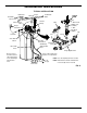
Installation Instructions TURN OFF WATER SUPPLY Nozzle Venturi Assembly 1. Close the main water supply valve, located near the well pump or water meter. Top Cover Brine Tank Overflow Elbow Nut Ferrule 2. Open all faucets to drain all water from house pipes. NOTE: Be sure not to drain water from the water heater, as damage to the water heater elements could result.
Installation Instructions COMPLETE INLET AND OUTLET PLUMBING Measure, cut, and loosely assemble pipe and fittings from the main water pipe to the inlet and outlet ports of the water softener valve. Be sure to keep fittings fully together, and pipes squared and straight. Be sure hard water supply pipe goes to the water softener valve inlet side. Electrical Shock Hazard Install metal ground clamp to metal house water supply pipe before beginning installation.
Installation Instructions TEST FOR LEAKS ADD WATER AND SALT TO THE SALT STORAGE TANK To prevent air pressure in the water softener and plumbing system, complete the following steps in order: 1. Fully open two or more softened cold water faucets close to the water softener, located downstream from the water softener. Excessive Weight Hazard Use two or more people to move and lift salt bags. Failure to do so can result in back or other injury. 2.
Water Softener Setup TOUCH SCREEN Touch Screen Controls for programming the water softener are displayed on a touch screen, located on the softener’s front panel (See Figure 17). On-screen “buttons” appear as rectangular outlines with rounded corners and change with each display (See Figures below). Button presses are acknowledged with a “beep.” NOTE: Before cleaning the touch screen to remove fingerprints, unplug the transformer. The controller’s memory items (including clock time, water hardness, etc.
Programming Your E-Z Touch Water Softener SOFTENER STATUS SCREEN SALT LEVEL BUTTON During normal operation, the softener’s display shows a screen like the one in Figure 20, below. The display automatically returns to this screen from other screens after 4 minutes of inactivity. For the “Low salt” indicator to work, whenever you add salt to the softener, you must reset the salt level indicator on the display to match the new level of salt in the tank.
Programming Your E-Z Touch Water Softener SET LANGUAGE SET CONTRAST When the softener’s electronic control is first powered up, the setup procedure prompts you to set the language (See Page 12). To change the language: The contrast of the softener’s display screen may be adjusted to optimize its readability. Depending on the ambient lighting conditions, you may want to increase or decrease the contrast from the medium level that is the default when the electronic control is first powered up.
Programming Your E-Z Touch Water Softener RECHARGE BUTTON SET RECHARGE TIME The long button at the bottom of the softener status screen (See Figure 29) will show recharge status, including whether a recharge is scheduled (See Figure 41). During a recharge cycle, a countdown clock is displayed in the button (See Figure 32). When the softener’s electronic control is first powered up, the default time for starting an automatic recharge is 2:00 a.m.
Programming Your E-Z Touch Water Softener SCHEDULE A RECHARGE SETUP BUTTON To schedule a recharge for the next preprogrammed recharge time (2:00 a.m., or as set on Page 15): The SETUP button on the softener status screen is used to set items of basic operating information: =Set current time =Set water’s hardness =Set recharge time =Set water’s iron level =Advanced setup (Accesses more items that can 1. Press the RECHARGE button at the bottom of the softener status screen (See Figure 37). be set.
Programming Your E-Z Touch Water Softener SET HARDNESS SET IRON LEVEL When the softener’s electronic control is first powered up, the setup procedure prompts you to enter your water’s hardness (See Page 12). To change it: The softener’s electronic control can adjust cycle times to compensate for ferrous (clear water) iron in the water. When the softener’s electronic control is first powered up, the iron level is set at 0. 1. Press the SETUP button on the softener status screen (See Figure 45).
Retrieving Information from the Water Softener Management System INFO (INFORMATION) BUTTON The INFO button on the softener status screen is used to look up the following information about the softener and its operations: =Current water flow =Average daily water use =Water used today =Capacity remaining =Days in use =Total recharges FIG. 51 To display one of these screens: 1. Press the INFO button at the center of the softener status screen (See Figure 50). FIG. 52 FIG. 50 FIG. 53 2.
Customizing Features / Options SET CLEAN FEATURE The Clean Feature with Sediment Guard technology is beneficial on water supplies containing ferrous (clear water) iron. The default setting is OFF. When set to ON, an additional backwash and fast rinse cycle will occur first, preceding the normal regeneration sequence. This provides extra cleaning of the resin bed before it is regenerated with the salt brine. To conserve water set this feature OFF if your water supply does not contain iron or sediments. 6.
Customizing Features / Options SET SALT EFFICIENCY 7. Press the button next to ON to enable this feature (or OFF to disable it) and then press the RETURN ( ) button. When this feature is ON, the water softener will operate at salt efficiencies of 4000 grains of hardness per pound of salt or higher (May recharge more often using smaller salt dosage and less water).
Customizing Features / Options SET UNITS The softener can be set to display values such as volume and water hardness in either English or Metric units. In addition the clock may be set to display time in either 12-hour (AM/PM) or 24-hour format. VOLUME UNITS TIME FORMAT To select between gallons and liters as volume units: To select between 12-hour (AM/PM) and 24-hour time format: 1. Press the SETUP button on the softener status screen. 2.
Customizing Features / Options POWER OUTAGE MEMORY RESTORE FACTORY SETTINGS If electrical power to the water softener is lost, “memory'' built into the electronic control circuitry will keep all settings for up to six hours. While the power is out, the display is blank and the water softener will not regenerate. When electrical power is restored, the following will occur. This feature resets the softener’s electronic controller to its initial startup condition.
Routine Maintenance ADDING SALT CLEANING THE NOZZLE & VENTURI Lift the salt hole cover and check the salt storage level frequently. If the water softener uses all the salt before you refill it, you will experience hard water. Until you have established a refilling routine, check the salt every two or three weeks. Always add if less than 1/4 full. Be sure the brinewell cover is on. NOTE: If using potassium chloride (KCl), do not fill above level 4 on the brinewell decal.
Troubleshooting AUTOMATIC ELECTRONIC DIAGNOSTICS OTHER INITIAL DIAGNOSTICS This water softener has a self-diagnostic function for the electrical system (except input power and/or water meter). The water softener monitors electronic components and circuits for correct operation. If a malfunction occurs, an error code appears in the display. NOTE: Be sure water is in contact with the salt, and not separated by a salt bridge (See "Breaking A Salt Bridge" section).
Troubleshooting MANUAL ADVANCE REGENERATION CHECK If water does not enter the tank, look for an obstructed nozzle, venturi, fill flow plug, brine tubing, or brine valve riser pipe. This check verifies proper operation of the valve motor, brine tank fill, brine draw, regeneration flow rates, and other controller functions. Always make the initial checks first. 4. After observing fill, press the ADVANCE VALVE button to move the softener’s valve into the brine position.
Softener Exploded View 26 Valve Assembly See Pages 28 - 29 for parts 27 42 28 43 29 1 122 2 6 3 4 30 7 5 31 8 32 34 9 35 33 10 36 25 8 11 37 7 24 6 5 23 22 38 21 20 40 19 18 12 41 17 13 14 15 26 39 16
Softener Parts List Key No. 1 2 3 4 5 6 7 8 9 10 11 12 Part No. 7170296 7170254 7077870 7170270 7105047 7265025 7176292 7088033 7247996 0502272 7221746 7113016 13 7131365 15 7308881 14 16 7142942 7116713 17 0516924 19 7170288 21 7220627 18 20 22 23 24 25 ¢ 0516211 7308904 0516947 7097202 0513860 7168647 7310202 Key No. Description O-Ring, 2-7/8” x 3-1/4” O-Ring, 13/16” x 1-1/16” Top Distributor O-Ring, 2-3/4” x 3” Repl.
Valve Exploded View 100 101 102 144 103 143 104 105 142 106 141 140 139 138 110 113 cross-section view 114 125 135 121 112 seal 136 108 111 wear-strip 137 109 107 115 134 120 116 133 132 117 118 131 130 129 122 119 126 127 124 128 28 123
Valve Parts List Key No. Part No. 100 7224087 Screw, #8-32 x 1” (2 req.) 102 7231393 Motor Plate 101 103 104 105 106 107 108 109 110 111 112 113 114 115 116 117 118 7286039 0900857 7171250 7283489 7169180 0900431 7271270 7170288 0501228 7170327 7173024 7174313 7185500 7173032 7185495 7172989 7171187 119 7129889 121 7271204 120 122 123 124 7089306 7311127 7094898 7101548 Key No. Description 125 Motor (incl. 2 ea. of Key No.