
Tech Sheet

FOR SERVICE TECHNICIAN’S USE ONLY
NOTE: This sheet contains important Technical Service Data.
W11266094A
Tech Sheet
Do not remove or destroy
DANGER
Electrical Shock Hazard
Only authorized technicians should perform diagnostic
voltage measurements.
After performing voltage measurements, disconnect
power before servicing.
Failure to follow these instructions can result in death
or electrical shock.
WARNING
Electrical Shock Hazard
Disconnect power before servicing.
Replace all parts and panels before operating.
Failure to do so can result in death or electrical shock.
Specications
ELECTRICAL SUPPLY:
(Under load) 60 Hz, 120 VAC
LOWER SPRAY ARM ROTATION:
12 to 40 rpm
SUPPLY WATER FLOW RATE:
To ll 2 qt (1.9 L) in 27 seconds, 120 psi maximum, 20 psi minimum
UPPER SPRAY ARM ROTATION:
12 to 30 rpm
SUPPLY WATER TEMPERATURE:
120°F (49°C) (Before starting a cycle, run water from sink faucet until
hot.)
WATER CHARGE:
0.9 gal. (3.5 L) approximate
Pin
1
Pin 1
1
2
3
Locking tab
Hinge hook
Underside of
housing base
4
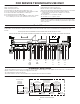
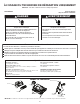
Rast Connector Pinout
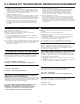
When performing live voltage measurements, you must do the following:
Voltage Measurement Safety Information
Verify the controls are in the off position so that the appliance does not start when energized.
Allow enough space to perform the voltage measurements without obstructions.
Keep other people a safe distance away from the appliance to prevent potential injury.
Always use the proper testing equipment.
After voltage measurements, always disconnect power before servicing.
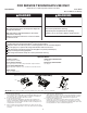
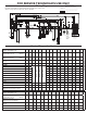
Steps to Access Control for Servicing
1. Connector Box Removal:
Press inward on the retainer tabs as indicated while lifting up on the
connector box. This can be done with a screwdriver or similar tool
from either the top or bottom side of the control.
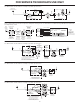
2. Connector Brace Removal:
Locate the 3 brace locking tabs as shown. Push each tab in the
direction required while applying light downward rotational force on
the brace. It is easiest to unlock one tab at a time, working from one
end of the brace to the other.
3. Once all 3 tabs are unlocked, pivot the brace to allow removal and
gain access to the wiring harness connectors and control for required
servicing.
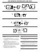
4. Connector Brace Reattachment:
Attach the brace hinge hooks into holes in the hinge tabs on control
housing base. Pivot brace until all 3 locking tabs snap into housing
lid. Make sure the harness wires lay at and are not pinched.
5. Connector Box Reattachment:
Position the connector box over P4 and P5 connectors, insert the
retainer tabs into brace mounting holes, and snap box onto control
housing lid. Make sure box is sitting ush against both the brace and
housing and harness wires are at and not pinched.
IMPORTANT: Connector box and brace must be reattached to control when service is completed.
Control Assembly
1