
Tech Sheet

4
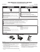
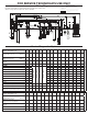
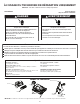
Diverter Valve
See “Meter Check of Loads and Fuses” to diagnose possible open fuse issues.
L1
BK
N
P4-2
P7-4
P7-3
P7-6
P4-1
N
NEU
WH
BLBU
BU
Pin 3
Broche 3 Broche 1
Pin 1
N.O.
Pilot L1 Relay
(Also see Door
Switch Circuit.)
Fuse
F601
Fusible
F601
Electronic Control
Test hole for P7-6 may crowd P7-4
Recommend using test hole on P7-3.
Electronic
Control
Triac
Diverter Motor
1,100
Ω
Ω
- 1,400Ω
Ω
120V, 60Hz, 3W
Sensor
Input
Switch closes momentarily
and then reopens as the diverter
reaches each potential diverter position.
Diverter Position
Switch
Test hole for P11-4 may crowd P11-3.
Recommend using test pad on P11-2.
P11-4
P11-3
P11-2
3V
N.O.
Diverter Sensor
P5-2
Fuse F600
Fusible F600
Relais d'alimentation
L1(voir également
le circuitdu
contacteur porte)
Module de commande électronique
Electronic Control
Module de commande électronique
Electronic Control
Module de commande électronique
Module de
commande
électronique
La cosse de test P7-6 peut obstruer P7-4.
Utiliser la cosse de test sur P7-3.
Capteur Diversion
Capteur -
Entrée
Le contacteur se ferme momentanément,
puis s'ouvre de nouveau lorsque le module de diversion
atteint chaque position potentielle de diversion.
Contacteur -
positionclapet
de diversion
La cosse de test P11-4 peut obstruer P11-3
.
Utiliser la cosse de test sur P11-2.
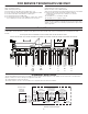
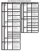
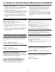
Vent (not all models)
See “Meter Check of Loads and Fuses” to diagnose possible open fuse issues.
L1
BK
N
P4-2
P5-2
P7-3
P7-1
P4-1
NEU
N
W
BL
H
BU
BU
K2
Fuse F601
Pin 1
Broche 1 Broche 3
Pin 3
N.O.
VENT MAX MOTOR
600 -1800 Ω
120 V, 60 Hz, 6 W
Pilot L1 Relay
(Also see Door
Switch Circuit)
Electronic Control
Fuse F600
Electronic Control
Module de commande électronique
Module de
commande
électronique
Relais dÊalimentation
L1(voir également
le circuit du
contacteur porte)
Fusible F601
Fusible F600
MOTEUR DE
VENTILATEUR MAX
600 -1800 Ω
120 V, 60 Hz, 6 W
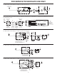
AC Fan (not all models)
See “Meter Check of Loads and Fuses” to diagnose possible open fuse issues.
DC Fan (not all models)
L1
BK
N
P4-2
P5-2
P7-3
P7-1
P4-1
N
NEU
WH
BLBU
BU
Pin 1
Broche 1Broche 3
Pin 3
N.O.
AC Fan Motor
120 V, 60 Hz
130 - 155
Ω
Pilot L1 Relay
(Also see Door
Switch Circuit)
Electronic Control
Electronic Control
Fuse F600
Fuse F601
Triac
Module de commande électronique
Module de
commande
électronique
Relais dÊalimentation
L1(voir également
le circuit du
contacteur porte)
Fusible F601
Fusible F600
Moteur du ventilateur CA
120 V, 60 Hz
130 - 155 Ω
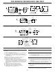
Electronic Control
Electronic Control
(Red stripe on plug)
P11-2
P11-1
DC Ref
MAR
BR
MAR
BR
Pin 1
Borche 1
Borche 3
Pin 3
Fan Motor
31K
Ω - 41K
Ω
5 V DC, 1W
Must measure resistance
with correct polarity and
disconnected from controls.
5V
_
+
Module de commande électronique
Module de commande électronique
(liseré R sur fiche
de branchement)
(Red stripe on plug)
(liseré R sur fiche
de branchement)
Moteur ventilateur
31K
Ω - 41K
Ω
5 V DC, 1 W
La résistance doit être mesurée
avecla polarité correcte et déconnectée
des modules de commande.
Ref CC
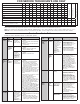
Service Diagnostics Cycle Notes
To invoke the Service Diagnostics cycle, perform the following while
in Standby:
Press any 3 keys in the sequence 1-2-3-1-2-3-1-2-3 with no more
than 1 second between key presses.
The Service Diagnostics cycle will start when the door is closed.
To rapid advance 1 interval at a time, press START/RESUME.
Rapid advance may skip sensor checks as some checks require 2
complete intervals.
NOTE: The Service Diagnostic cycle will pause when the door
is opened and resume automatically upon door closure.
No Start/Resume key press is required to resume.
Invoking Service Diagnostics cycle clears all status and last run
information from memory and restores defaults. It also forces the
next cycle to be a Sensor Calibration cycle. Calibration cycle may
add additional rinses prior to the nal rinse to ensure clear water
and then calibrates the OWI during the ll at the beginning of the
nal rinse.
Drain and wash motors will pulsate on and off.
Last Ran cycles and options returned to default.
Last Ran Delay returns to the default delay setting.
Operating state returns to Standby upon completing or
terminating the Service Diagnostics cycle.
Press Hi Temp or cycles key in this interval to clear customer error
history.
Thermistor (temperature sensor) checks:
Turn Clean LED on if thermistor is in its normal temperature range
of 32°F–167°F (0°C–75°C).
Turn Sanitized LED on if Fill temperature is above 156°F (69°C).
OWI (Optical Soil Sensor) Checks:
Check OWI sensor for the presence of water during 5 second
pause in interval 16 and turn on Clean LED in interval 14 if water
detected.
Check OWI sensor for presence of bulk soil during interval 12 and
turn on Clean LED in interval 11 if bulk soil is detected.
Diverter will be on continuously in intervals 14 and 13. In all other
intervals, diverter will be on only until it reaches the intended position
for that interval.
DC fan motor is on during upper rack washing intervals.
3
4
21
5
6
FOR SERVICE TECHNICIAN’S USE ONLY