
Specification
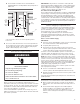
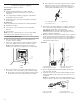
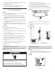
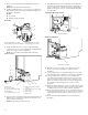
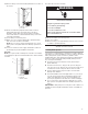
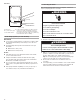
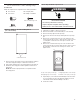
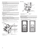
Table Of Contents
- Ice Maker SAFETY
- INSTALLATION INSTRUCTIONS
- SÉCURITÉ DE LA MACHINE À GLAÇONS
- INSTRUCTIONS D’INSTALLATION
- Déballage de la machine à glaçons
- Exigences d’emplacement
- Spécifications électriques
- Spécifications de l’alimentation en eau
- Vacances ou longue période d’inutilisation
- Raccordement à la canalisation d’eau
- Installation de la pompe de vidange (sur certains modèles)
- Raccord au drain
- Inversion du sens de la porte – porte à ouverture latérale uniquement
- Ajustement de l’aplomb
- Nettoyage
- SEGURIDAD DE LA FÁBRICA DE HIELO
- INSTRUCCIONES DE INSTALACIÓN
- Cómo desempacar la fábrica de hielo
- Requisitos de ubicación
- Requisitos eléctricos
- Requisitos de suministro de agua
- Vacaciones o tiempo prolongado sin uso
- Conexión del suministro de agua
- Instalación de la bomba de desagüe (en algunos modelos)
- Conexión de desagüe
- Reversión de puertas— Solo lado de apertura
- Nivelación
- Limpieza

6
3. Remove the old drain tube and clamp attached to the ice
maker bin.
NOTE: Discard old drain tube and clamp.
4. Install new drain tube (5/8" I.D. x 5¹⁄
8
") from ice maker bin to
drain pump reservoir inlet using new adjustable clamps. See
“Drain Tube” illustration.
NOTES:
■ Do not kink.
■ Trim tube length if required.
Drain Tube
5. Install vent tube (5/16" I.D. x 32" [81 cm]) to drain pump
reservoir vent. Use one of the supplied 5/8" small adjustable
clamp. See “Parts Locations” illustration.
NOTE: Do not install household drain tube at this time.
Parts Locations
6. Remove power cord clamp and ground screw attached to ice
maker power cord, which is mounted to the unit base. See
“Parts Locations” illustration.
NOTE: Clamp and screw will be reused.
7. Slide drain pump into the ice maker base on the right side.
The pump mounting tab should slip into the rectangular slot
in the ice maker base. It will be necessary to tip the pump
slightly to slip into the slot. See “Drain Pump Mounting Tab
Slot” illustration.
Drain Pump Mounting Tab Slot
Drain Pump Installed
8. Align the 2 screw holes at the rear of the pump. Use two
#8-32 x 3/8" screws, supplied. See “Parts Locations”
illustration.
9. Connect drain tube to ice maker bin outlet (5/8" I.D.), using
7/8" adjustable clamp, supplied. See “Drain Tube” illustration.
10. Coil ice maker power cord into a 4" (10.2 cm) diameter
coil. Wrap electrical tape around the power cord in several
places to keep the cord in a coil. Locate coiled power cord
between the drain pump and side of enclosure and plug into
the receptacle of the drain pump. See “Parts Locations”
illustration.
11. Attach the drain pump power cord to ice maker unit base with
clamp and screw (removed in Step 6) that was used to attach
ice maker power cord. See “Parts Locations” illustration.
12. Place new rear panel (small one for 15" ice makers, large one
for 18") against the back of the ice maker. Route the vent tube
and drain pump discharge tube through cutouts in the rear
panel.
13. Secure rear panel with original screws. See “Rear Panel”
illustration.
A
B
C
D
A. 7/8" adjustable hose clamp
B. Drain tube (ice bin to drain pump)
C. 7/8" adjustable hose clamp
D. Drain pump reservoir inlet
C
H
I
G
F
E
D
B
A
A. Vent tube
B. 5/8" hose clamp
C. Drain pump discharge tube
D. Drain pump
E. Ice maker unit power cord
F. #8-32 x 3/8" pump mounting
screws
G. Drain pump power cord, clamp
and screw
H. Plastic retainer
I. Wiring cover
A
A. Mounting tab slot
A
A. Drain pump installed