T E C H M A N UA L WM&FD 021014
We manufacture, test and certify 100% of our wine cooling units in the USA. By sourcing the best components and closely controlling our manufacturing processes, we can assure the highest-quality, lowest defect manufacturing rates in the industry. Copyright © 2012. CellarCool. All rights reserved. This manual, the product design, and the design concepts are copyrighted by CellarCool, with all rights reserved.
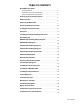
TABLE OF CONTENTS Quick Reference Guide Evaporator Unit. . . . . . . . . . . . . . . . . . . . . . . . . . . . . . . . . . . . . . . . . . 2 Controller Layout & Specifications. . . . . . . . . . . . . . . . . . . . . . . . 3 Fully Ducted Unit & Specifications. . . . . . . . . . . . . . . . . . . . . . . . 4 Receiving & Inspecting The System. . . . . . . . . . . . . . . . . . . . . . . . . 5 Before You Start . . . . . . . . . . . . . . . . . . . . . . . . . . . . . . . . . . . . . . . . . . . .
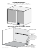
QUICK REFERENCE GUIDE WM Evaporator Unit (Fan Coil Unit) Front / Side View Evaporator Unit (Fan Coil Unit) °F Filter Grille Controller WM Evaporator Unit (Fan Coil Unit) Rear / Side View Mounting Key Hole (X4) THROUGH THE WALL Option 1 Knock Out For Wiring Knock Out For Suction Line Knock Out For Liquid Line Knock Out For Drain Line Circular Connection INSIDE CELLAR Option 2 Liquid Line Knock Out Suction Line Knock Out Page 2 | 1-855-235-5271 Knock Out For Drain Line Knock Out For Wiring WM&FD 021014
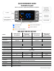
QUICK REFERENCE GUIDE Controller Layout °F °F Refer to page 36 for complete listing of buttons and symbols. High History Scroll Button °F Inactive Cellar Pre-Chill (Press and hold 3-5 sec) °F °F °F Low History Scroll Button View Set Point Change Set Point (Press and hold 3-5 sec) Power On/Off Compressor On Unit is in Pre-Chill Mode Fans are On Alarm is Present Unit is in Anti-Frost Mode WM UNIT SPECIFICATIONS Model Cellar Size (cu. ft.) Dimensions 20.5”w x 15.625”h x 16.
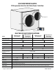
QUICK REFERENCE GUIDE FD Evaporator Unit (Fan Coil Unit) Front / Side View Supply Air Return Air °F Keypad Duct Plenum DUCTED FD UNIT SPECIFICATIONS 3500 Condenser (Air Cooled Condensing Unit) 3500 Evaporator (Fan Coil Unit) Model Cellar Size (cu. ft.) Dimensions 1000 20.5”w x 15.625”h x 20”d BTUh with 90° air entering the Condenser Coil 2000 12”w x 13.5”h x 18”d 20.5”w x 15.625”h x 20”d 3120 200 CFM 5000 Condenser (Air Cooled Condensing Unit) 5000 Evaporator (Fan Coil Unit) 12”w x 13.
RECEIVING & INSPECTING THE SYSTEM Receiving and Inspecting the System • Lift only at the designated hand hold locations on the shipping container or fully support the unit from • • • underneath. A shipment may include one or more boxes containing accessories. Before opening the container, inspect the packaging for any obvious signs of damage or mishandling. Write any discrepancy or visual damage on the Bill of Lading before signing. Allow the condensing unit to sit for 24 hours prior to start up.
BEFORE YOU START 1. Inspect all components prior to installation. If damage is found, please contact your distributor or CellarCool Customer Service at 1.800.343.9463. 2. The Condensing Unit requires a dedicated 115-volt 20-amp circuit. Use a surge protector with the unit. Do not use a GFI (Ground Fault Interrupter) line. 3. It is REQUIRED to install a drain line to remove condensation from the Evaporator Unit (Fan Coil Unit). 4.
PREPARING THE WINE CELLAR The performance and life of your system is contingent upon the steps you take in preparing the wine cellar. Note: Improperly preparing your enclosure or incorrectly installing your unit may cause unit failure, leaking of condensation, and other negative side effects. IT IS HIGHLY RECOMMENDED THAT YOU OBTAIN THE ASSISTANCE OF A WINE STORAGE PROFESSIONAL.
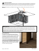
Unobstructed Airflow Unobstructed airflow to and from the system is critical for the system’s overall performance and life-span. A minimum three-foot clearance (five foot is ideal) area is crucial. The air the fans blow needs to circulate and either dissipate or absorb heat from the space, the more air to exchange the more efficient the system will operate. Note: Avoid attempting to camouflage the unit. This will restrict airflow and thus the systems’s ability to work efficiently.
Ventilation The necessity of dissipating heat away from the condensing unit is critical to the performance and cannot be overstated. As the system operates and cools, a greater amount of heat is generated on the condensing side of the system. Adequate ventilation is required in order to dissipate heat away from the condensing unit. If ventilation is inadequate, the exhaust will heat up the area or room and adversely affect the systems ability to cool.
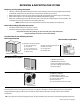
PREPARING AND INSTALLING THE WALL MOUNT EVAPORATOR UNIT (FAN COIL UNIT) Required Tools: • • • Drill 5/32” Drill Bit 1/4” Socket Drill Bit • • • 1/4” Wrench • Phillips Head Screwdriver • Tape Measure • Brazing Torch Drywall Saw Ladder • • • Level Pliers Pencil DRAIN PAN Power 3/8” Suction 1/4” Liquid 1. Remove the knockouts for the drain line, line set, and electrical on the bottom or rear of the unit depending on your installation preference. 2. Remove the insulation from the knockout holes. 3.
INSTALLING THE WALL MOUNTED EVAPORATOR (FAN COIL UNIT) 1. Locate 2 wall studs in the desired mounting location spaced 16” on center. 2. Mark vertical lines on each stud 16” apart. 3. Mark an intersecting, horizontal line at the desired height of the unit. 4. Make a mark on each stud 13 ½” down from the intersection of the horizontal and vertical lines. Note: The top of the unit needs to be installed at a minimum of 6” and a maximum of 18” from the ceiling. 5.
INSTALLING THE WALL MOUNTED EVAPORATOR (FAN COIL UNIT) 9. Using 1/4” and 1/2” copper tubing, route the liquid and suction lines through the knockouts in the wrapper. Be sure to extend the tubing far enough outside of the wrapper to extend through the wall if necessary. Note: ½” copper tubing will slip over the 3/8” suction line on the evaporator for an easy connection. 10. Remove the solenoid coil and wrap the solenoid valve with a wet rag to prevent overheating. 11.
DRAIN LINE Condensation Drain Line The condensation drain line tube is used to remove excess condensation from the evaporator unit to a proper discharge location. It is important that the drain line tube is properly connected and used to prevent leakage and other problems associated with excess condensation. Failure to use the condensation drain line tube will void the warranty on the unit. Drain Line All systems come with a drain line for removal of excessive condensate.
NOTES Page 14 | 1-855-235-5271 WM&FD 021014
PREPARING THE FULLY DUCTED EVAPORATOR (FAN COIL UNIT) 1. Remove the knockouts for the drain line, line set, and electrical on the bottom or rear of the unit depending on your installation location. 2. Remove the insulation from the knockout holes. 3. Route the air sensing probe from the cellar to the evaporator unit. 4. Follow the directions on page 18 to mount the remote keypad and run the communication cable to the evaporator unit. www.cellarcool.
INSTALLING THE FULLY DUCTED EVAPORATOR (FAN COIL UNIT) 1. If mounting the unit to a wall see steps 1-8 of the instruction for installing the Wall Mounted Evaporator Unit. 2. Using 1/4” and 1/2” copper tubing, route the liquid and suction lines through the knockouts in the wrapper. Be sure to extend the tubing far enough outside of the wrapper to extend through the wall if necessary. Note: ½” copper tubing will slip over the 3/8” suction line on the evaporator for an easy connection. 3.
INSTALLING THE FULLY DUCTED EVAPORATOR (FAN COIL UNIT) 14. Connect the air sensing probe to the circular connector located in the lower left side of the housing. 15. Install the supplied black strain relief to secure the power supply wires and air sensing probe wire in the housing. 16. Route the communication cable from the remote display into the evaporator housing 17. Connect the communication cable to the circular connector located in the lower left corner of the housing. 18.
REMOTE KEYPAD: INSTALLATION AND CONFIGURATION If you have a system with a remote keypad, please review this section for installation. Note: 50 feet of communication line is included, the keypad can be installed up to 300 line feet away. Longer lengths of communication line can be ordered by calling 1-800-343-9463 ext. 751. Red Wire Black Wire Route the communication line from the evaporator unit to the desired keypad location. Remove the wall mount bracket from the display housing.
WM&FD WIRING DIAGRAM Black White Black Blue Neutral Line Use Copper Conductor Only 1 4 (1) 1 4 (4) Green Green Green Black White Ref. Solenoid Blue Black Black White White Blower Fan Red 1 4 1 4 www.cellarcool.
WM&FD WITH HUMIDITY WIRING DIAGRAM Black White Black Blue Neutral Line 1 4 (1) 1 4 (2) Black Black White Black Blue Black Use Copper Conductor Only 1 4 (3) 1 4 (4) Ref.
3500 CONDENSING UNIT WIRING DIAGRAM www.cellarcool.
5000 CONDENSING UNIT WIRING DIAGRAM LEGEND: TERMINAL BOARD BD # SERVES GROUND 2 3 4 5 6 7 8 9 10 GREEN UK GREEN/YELLOW STRIPE L1-115V-HOT BLACK RED UK-CAN 115V-NEUTRAL WHITE BLUE UK CC HEATER BLACK COMP GND GREEN H-COMP BLACK N-COMP WHITE H-COND FAN BLACK LINE H-LP-HP BLACK COMPRESSOR CRANKCASE LOAD H-LP-HP BLUE HEATER WHITE (NEUTRAL) BLACK 1 M UP S START CAPACITOR 2 L FAN (CONDENSER) 3 BLUE RED 1 COLOR 1 C R S YELLOW TD=TIME DELAY, DELAY ON BREAK RELAY COMPRESSOR TERMINAL OVERLOAD GREEN
5000 CONDENSING UNIT WIRING SCHEMATIC H POWER 115v 60 HZ N 4 CC HEATER START CAPACITOR COMP CONTACTOR CURRENT RELAY 6 OL 3 COMPRESSOR 9 HP 10 LP TD CC CC HP LP TD COMP CONTACTOR HI PRESS SWITCH LO PRESS SWITCH TIME DELAY 7 6 8 LOW AMBIENT CONTROL COND. FAN www.cellarcool.
ACTIVE HUMIDITY OPTION OVERVIEW ACTIVE HUMIDITY SPECIFICATIONS Power Consumption 0.2 amps @ 120V/60 Hz dBA TBD Humidistat Range 30-90% RH Humidistat Accuracy ± 1% Humidistat Adjustment Increments 1% Water Supply Feed Rate 0.63 gph @ 40 psi Accessory Included with Active Humidity Option: (1) 25 ft. Humidistat Cable (1) Dayton Humidistat Use of the Active Humidity Option Humidity may fluctuate in the wine cellar.
HUMIDISTAT INSTALLATION Routing the Wiring 1. Plug the circular connector from the humidistat cable into the circular connector on the unit as shown in Figure 1. 2. Route the wire from the unit to the desired humidistat location. Figure 1 Removing the Cover 1. Move both slide controls to the bottom position. 2. Use a screwdriver to loosen the screws at the bottom of the humidistat as shown in Figure 2. Slide controls Figure 3 3. Carefully remove the cover as shown in figure Figure 3.
HUMIDISTAT INSTALLATION Wall anchors Mounting With a Wall Mount Plate 1. Make sure the humidistat is unplugged before installing the unit. 2. Position the wall mount plate on the wall or junction box and ensure the plate is level and covers the junction box completely. 3. Pull the electrical wires through the hole in the wall mount plate. 4. Drill holes in the wall through the 2 mounting holes in the back of the wall plate as shown in Figure 5 and insert anchors into the holes. 5.
PREPARING THE CONDENSING UNIT Electrical Needs The Condensing Unit requires a dedicated 115-volt 20-amp circuit. The unit draws a large inrush current for about one second the instant the compressor starts. With a dedicated circuit and circuit breaker, the condensing unit will have sufficient power for effective operation. (The compressor is controlled by a low pressure switch mounted on the condensing unit.
PREPARING THE CONDENSING UNIT (continued) Installing the Condensing Unit The condensing unit can be installed inside a well ventilated area of the home, but it is typically installed outside. Exterior applications will require the use of a protective housing, and the amount of sun exposure should be considered when selecting the placement of the condensing unit .The condensing unit requires a dedicated 20 amp circuit, non-GFI.
LINE SET PIPING DIAGRAMS These are two options for running the line set from the coil to the condensing unit. Option 1 is specifically for when the system is installed with the condensing unit below or leveled to the coil. Option 2 is for when the system is installed with the condensing unit at a higher elevation than the coil. Option 1 LEGEND LLS Liquid Line Solenoid TXV Thermal Expansion Valve COMP REC Compressor Receiver EVAP. Evaporator O.D. Outer Diameter Option 2 www.cellarcool.
INSTALLING THE CONDENSING UNIT Refrigerant Piping Procedures When installing/routing the lines set, cap both ends of each tube to prevent material or debris from entering the tubing. Prior to connecting the piping, loosely connect the refrigerant gauges to the service ports of the suction and liquid line service valves. Purge the charging hoses with dry Nitrogen and tighten the hose connections.
INSTALLING THE CONDENSING UNIT Evacuation Connect evacuation type four valve gauge manifold to high and low pressure service valve ports on the condensing unit with the valve stems mid seated as when leak testing. Install service caps on valves and tighten them. Energize the liquid line solenoid valve (make sure there is fresh oil in the vacuum pump).
INSTALLING THE CONDENSING UNIT (continued) Measure Superheat If superheat is high and bubbles are present, add more refrigerant until it is clear. If superheat is low (around 4-6 degrees Fahrenheit) and bubbles are present in the sight glass, check for liquid refrigerant entering the compressor as evidenced by cool crankcase below 100- 110 degrees Fahrenheit and low discharge superheat. Adjust TXV setting in small increments to increase superheat and stop liquid from going to the compressor.
INSTALLING THE WALL MOUNT KIT 1. If removed, re-install the top onto the unit. 2. Connect the red wire from the display adapter to the upper (+) terminal on the display located on the front grille 3. Connect the black wire from the display adapter to the lower (-) terminal on the display 4. Align the front grill with the 4 ball studs on the housing. Push the front grill onto the balls studs until it snaps into place. 5.
INSTALLING THE DUCT PLENUM 1. If removed, re-install the top onto the unit. 2. Align duct plenum with the 4 ball studs on the housing. Push the duct plenum onto the balls studs until it snaps into place. 3. Using a Phillips head screwdriver, fasten the bottom two screws to fasten the plenum to the unit 4. Connect the supply and return duct work to the unit 5. Using duct tape or foil tape, seal the seam between the plenum and unit 6.
SYSTEM OPERATION Initial Start-Up When power is applied to the unit, the control will briefly display all symbols, and the Snow Flake symbol will be displayed (if unit is calling for cooling). There may be a brief delay prior to the evaporator fan turning on, as the fan will not turn on until the evaporator probe temperature drops below 70°F. When the evaporator fan is activated the Fan symbol will be displayed. The temperature control feature for the evaporator fan is a feature applicable to CellarCool.
CONTROLLER FUNCTIONS If your unit has a remote keypad then you will have the Remote Controller. High Temp / Pre-Chill Low Temp Display Set Point ON / OFF TEMPERATURE Button Normal Functions ON/OFF • The ON/OFF button allows the customer the convenience of turning the refrigeration system ON or OFF, from the control panel. This feature does not disconnect power from the unit. In order for the power to be shut off from the unit, the power cord must be unplugged from the wall receptacle.
Set 1. Press the “Set” button once and it will display the Set Point. After approximately 5 seconds, the display will return to normal operation and display the Air Sensing probe temperature. 2. Press the “Set” button once and it will display the Set Point. Press the up and down arrows to change the set point. Press the Set button again and the numbers will blink, confirming the change in Set Point. 3.
CPSM Mode Press the “Set” and the “Down Arrow” buttons simultaneously, for 3-5 seconds, and you will access the “Customer Preference Selection Mode” (CPSM). The CPSM allows the customer to “Fine Tune” the Control Operating System to their applicable choice. The following CPSM options are available for adjustment: Fon – Humidity Management Enhancement: This parameter is normally set at 0, which should provide adequate relative humidity for the cellar.
MAINTENANCE SCHEDULE Monthly 1. Check coils 2. Check for unusual noise or vibration 3. Check the drain line to see if it is above the waterline if draining into a vessel. Quarterly 1. Use a vacuum with brush attachment to clean coils. Be careful not to crush coil fins when cleaning. Annually 1. Inspect for corrosion. 2. Check wiring connections and integrity of cords. 3. Pour a 50/50 bleach solution into the drain line every spring. www.cellarcool.
TROUBLESHOOTING GUIDE Unit has ice forming on the Evaporator Unit (Fan Coil Unit) Possible Cause Solution Evaporator filter or coil is dirty. Remove the filter and wash, then clean the coil with a vacuum. If coil is very dirty, use a spray bottle with a small amount of liquid dish washing detergent or coil cleaner. Spray coil, let set for 5 min, then flush with fresh water. There is something blocking the supply and or return air Remove blockage The evaporator fan is not turning on.
TROUBLESHOOTING GUIDE Unit leaks water Possible Cause Solution Evaporator Unit (Fan Coil Unit) is not level Evaporator Unit (Fan Coil Unit) should be level on the wall to prevent leaking. Drain line clogged or kinked Check drain line to make sure water can flow freely.
BYPASS TEST PROCEDURE NOTE: If instructed by a CellarCool representative, follow the directions below to test the cooling unit using the bypass plug provided in the accessory kit. 1. Disconnect power from the evaporator unit 2. Loosen the two screws on the front of the grille or duct plenum 3. Pull the grill or duct plenum away from the evaporator unit 4. Remove the screw securing the control panel in place 5. Slide the control panel down, out of the evaporator housing.
NOTES www.cellarcool.
TECHNICAL ASSISTANCE CellarCool Customer Service is available Monday through Friday from 8:00 a.m. to 4:00 p.m. Pacific Time. The customer service representative will be able to assist you with your questions and warranty information more effectively if you provide them with the following: • The model and serial number of your CellarCool systems. • Location of unit and installation details, such as ventilation, ducting, construction of your wine cellar, and room size.
Split System Series Product Warranty Information CellarCool Product Terms and Conditions Including Product Limited Warranty And Product Installation Requirements For CellarCool Split System Series ATTENTION: PLEASE READ THESE TERMS OF USE CAREFULLY BEFORE INSTALLING YOUR CELLARCOOL COOLING SYSTEM. INSTALLING YOUR CELLARCOOL COOLING SYSTEM INDICATES THAT YOU ACCEPT AND AGREE TO EACH OF THE TERMS AND CONDITIONS SET FORTH HEREIN (“TERMS OF USE”).
• • • • • • • • • • Improper voltage supply Line set with screw connectors (high end and low end) Leaks found at the braze points when performing pressure check Unit that has been charged incorrectly Incorrect tubing diameter used on line set A unit that has been wired incorrectly Valve stem on condenser side Improper installation of P-Trap Lack of P-Trap (if required) Condensers that are installed outdoors or in elements that would affect operation without proper cover or housing.
1. allow the exclusion or limitation of incidental or consequential damages, or allow limitations on how long an implied warranty lasts, so the above limitations or exclusions may not apply to you. This limited warranty gives you specific legal rights, and you may have other rights, which vary from state to state. 2.
CellarCool only collects California sales tax for orders shipped within the State of California; CellarCool does not collect sales tax for orders shipped to other states. However, the Purchaser and the End User may be liable to the taxing authority in their state for sales tax and/or use tax on the Product. The Purchaser and the End User should each check with their state’s taxing authority for sales and use tax regulations. 6.
information, contact us via phone at 1-800-343-9463 or please send a letter via U.S. Mail to: Customer Service CellarCool Corporation 1738 E Alpine Ave Stockton, CA 95205 Email: support@cellarcool.com Web: www.cellarcool.com B. Technical Assistance. CellarCool Customer Service is available Monday through Friday from 6:30 a.m. to 4:00 p.m. PST.
CellarCool 1738 E. Alpine Ave Stockton, CA 95205 1(855) 235-5271 www.cellarcool.