I:_MI:_RSON THRU THE-WALL ELECTRONIC AIR Model INSTALLATION OPERATION SERVICE MANUAL NO. 846-0262 CLEANER Nos.
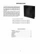
INTRODUCTION Thru-the-Wall electronic air cleaners are designed to provide maximum air cleaning in applications where a single central return air duct is employed, or where the central heating or air conditioning is in a limited access area. The Thru-the-Wall units may be installed in the wall such as in closet installations or in the ceiling with attic type installations. This manual contains essential information for locating, installing, operating and servicing your electronic air cleaner.
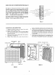
HOW YOUR AIR CLEANER WORKS (See figure 1.) Dirt laden air enters the unit from the room. It passes through the screen (A) first where large particles (hair, lint, etc.) are trapped. Smaller particles (smoke, dust, pollen, etc.) pass through this screen and enter the Ionizing Section (B). Here each tiny particle receives a positive electrical charge. These charged particles then enter the Collection Section (C) which consists of a series of aluminum plates.., alternate plates are charged positive.
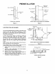
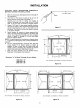
PREINSTALLATION 1 SUPPLY-AIR STUD t PLENUM WALL SURFACE-*- 6IN.-- AIR CLEANER WALL SURFACE -- "1 L,.- .'_ _ _,. RETU RN-AIR DUCT I I I J SUPPLY-AIR DUCT RETURN-AIR DUCT \ FURNACE // AIR STUD ,,.,-d TYPICAL WA LL LOCATI ON CLEANE 6 I . TYPICAL INSTALLATION Figure 4 USING DUCT EXTENSION Figure 5 TAPEJOINT LOCATING THE AIR CLEANER Your thru-the-wall Electronic Air Cleaner is mounted at the return-air duct inlet. (See figures 4 through 7.
3//4 ,, GRILLE DIM. 1000 CFM 1400 CFM A 16-15/16 23-7/8 28-7/8 B 9-7/16 16-7/16 21-7/16 C 18-7/16 25-3/8 30-3/8 D 19 " 2000 CFM 26 A 31 Refer to page 2 for model numbers and CFM cross references. FRAME ASSEMBLY REAR VIEW OF GRILLE AND CABINET Figure 8 WALL (OR CEILING) CABINET _2 MECHAN ICAL INSTALLATION Remember that allowance must be made for the grille to swing down so that the cell can be removed by. pulling it straight out of the cabinet. (Figure 9).
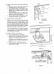
INSTALLATION CAUTION: READ INSTRUCTIONS COMPLETELY BEFORE STARTING THE INSTALLATION. CUT-OUT MARK 1. 2. •_ 4. Mark the cutout area. (See figures 8 and 12 through 14 for dimensions.) Drill holes at the corners of area to be cut out to permit insertion of saw blade. (See figure 11.) Carefully saw out wall or ceiling area exactly as marked. Remember the frame flange is only 3/4-inch wide. It will not cover an oversize or irregular cutout.
, Prepare air-cleaner cabinet for electrical connection as follows: a. b. c. d. 9. Determine location of power supply source which will dictate the location of electrical wiring. Three knockouts (figure 15) are located in upper right-hand corner of cabinet. A built-in "J" type junction box is included. Secure wiring with accepted hardware. The usual knockout location is at upper rear of cabinet. If an obstruction, prohibits this location, use either of the two other knockouts.
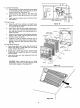
r-- 11. Connect Power Wires. a. b. c. 00 I Connect black and white wires from power supply to corresponding black and white wires in the air cleaner junction box. (See figure 18.) Connect ground wire (green or bare wire) from power source to green grounding wire in junction box. o _.._ i'_ II _ \\ _LACK h Install electrical enclosure cover with three screws. (See figure 2.) / / / b. c. d.
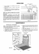
OPERATION 1. 2. 3. O N-OFF SWITCH Turn on furnace or air conditioner to get air flow through the duct. Press the lower section of "ON-OFF" rocker switch (Figure 21 ). Close the grille by rotating the cabinet (fig. 19). Lock two knurled screws. SAFETY1NTERLOCK SWITCH J OPERATING LIGHT '\ //0oi I into position on in position with OF Ir . i NOTE: Your air cleaner is equipped with an air sensing device. It may provide a short delay before the operating light comes on.
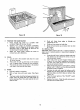
Figure 23 7, Figure 24 PREPARE THE WASH WATER: a. b. c. d. Place enough hot water in a suitable wash container (figure 23) to cover the cell. Dissolve four ounces of automatic dishwasher detergent, such as Calgonite, in the water. Liquid detergents used to wash dishes by hand are not strong enough for good cleaning. Shake the screen gently outside the house to remove heavy dirt collections. e. f. Flush cell frame along edges to dislodge trapped dirt or lint. Flush and rinse screenon both sides.
REPLACING AN IONIZING WIRE If one or more ionizing wires in the cell should break, usually caused by accidental damage, it can be replaced as follows: 1. Remove all pieces of broken wire. Make sure supports at each end are in good condition and not bent out of shape. 2. Hook the wire at one end onto the support. 3. Hold a finger against the support at other end (Figure 25) and hold ionizing wire between thumb and forefinger as shown.
REPAIR PARTS 11 "14 '15 12
Model Nos. 1OC1 3T-41 002 1 4C1 3T-41 002 2OC1 3T-41 002 WHEN ORDERING REPAIR PARTS, ALWAYS GIVE THE FOLLOWING INFORMATION AS SHOWN IN THIS LIST. 1. The PART NUMBER 2. The PART DESCRIPTION 3. The MODEL NUMBER 4. The NAME OF ITEM - Electronic Air Cleaner Always Order by "Part Number"... Never by "'Item No." PART NO. Item No. 1 2 3 4 5 6 7 8 9 10 11 12 13 14 15 10C13T Description PowerSupply Assembly .............................. Air SwitchAssembly (Inc!udesSpacer and Screws)..... _.
WHITE-RODGERS White-Rodgers Division, Emerson ElectricCo. 9797 Reavis Road, St. Louis, MO 63123 (314) 577-1300 Em I-\.