
Manual
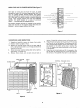

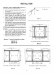

WALL SURFACE-*-
6IN.--
AIR CLEANER .'_
-- "1
L,.-
I
I
I
_ J
STUD
,,.,-d
_,. RETU RN-AIR
DUCT
TYPICAL WA LL LOCATI ON
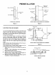
PREINSTALLATION
1 STUD
WALL SURFACE
RETURN-AIR
DUCT
\
AIR
CLEANE I
6 .
SUPPLY-AIR
t PLENUM
SUPPLY-AIR
DUCT
FURNACE
//
TYPICAL INSTALLATION USING DUCT EXTENSION
Figure 4 Figure 5
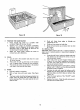
LOCATING THE AIR CLEANER
Your thru-the-wall Electronic Air Cleaner is mounted at the
return-air duct inlet. (See figures 4 through 7.) It works
equally well in either high or low wall installationsl or in
the ceiling. It can be used with any type of forced-air
heating or cooling system.
In most cases, return-air ducts are located just inside the
wall (or ceiling) grille. When the air cleaner is flush
mounted it will extend through the wall cutout and into
the return-air duct. If the return-air duct is located at a
distance from the wall (or ceiling), extend a connecting
duct to the rear of air cleaner frame with sheet metal
screws.
NOTE: Always tape all ductwork joints with duct tape to
prevent dirt-laden air from entering ducts.
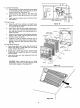
After deciding upon the exact,location, make.sure of the
following before cutting out wall or ceiling area:
1. Exact location of return-air duct behind the wall (or
ceiling).
2. Location is free of obstructions, such as steel support
beams, piping or electric wiring.
3. Access to inner areafor wiring connections.
4. Return-air duct is deep enough to accommodate air
, cleaner (6 inches, seefigures 4 through 8.)
5. Enough room is llft at a corner or wall offset to permit
installation of the grille. (See figure 8.)
TAPEJOINT
! CONNECTING I
WALL _ , DUCT I
(ORCEILING) _ _ JlJ
SURFACE m
6 IN._
7
AIR CLEANER _J
SCREWHOLES
STUD- (TOP, BOTTOMAND
SIDESOF CABINET)
RETURN-AIr
DUCT
/
TYPICAL INSTALLATION USING DUCT EXTENSION
Figure 6
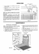
RETURN-AIR DUCT
J 14
A
IN. MINIMUM
A,RC'EANER
t I f
CEILING SURFACE 6 IN.
TYPICAL CEILING LOCATION
Figure 7