
Manual


3//4 ,,
GRILLE "
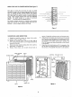
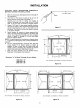
DIM. 1000 CFM 1400 CFM 2000 CFM
A
B
C
D
16-15/16
9-7/16
18-7/16
19
23-7/8
16-7/16
25-3/8
26
28-7/8
21-7/16
30-3/8
31
Refer to page 2 for model numbers
and CFM cross references.
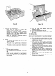
Figure 8
FRAME
ASSEMBLY
A
REAR VIEW OF GRILLE AND CABINET
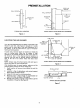
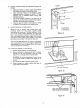
MECHAN ICAL INSTALLATION
Remember that allowance must be made for the grille to
swing down so that the cell can be removed by. pulling it
straight out of the cabinet. (Figure 9).
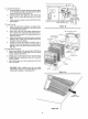
DUCT WORK CONNECTION
If the duct work to be used is larger or smaller than the
recommended framing sizes, a transition should be installed
between the duct work and the air cleaner to insure
maximum filtering efficiency. The expansion or contraction
rate of the transition should not exceed the ratio of 1 to 3.
(Seefigure 10)
Once the duct connection to the framing is completed, the
air cleaner frame (cabinet) may be inserted into the framing
cavity.
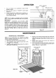
Before inserting the cabinet, one of the three knockouts
(figure 15) should be removed for insertion of the 120 VAC
input wiring.
After properly positioning the cabinet, it may be fastened
to the framing either by using the mounting holes in the
inside walls of the cabinet or the mounting holes in the
front flanges of the unit.
WALL
(OR CEILING)
ALLOW ROOM FOR
GRILLE TO
SWING OUT
CELL
, !
GRILLE
Figure 9
CABINET
_2
TRANSITIO N _,.'"_2 0_ l_ J
151
iA,',',,ox.I
.11I
oust ,/I I
UNIT OPENING
TRANSITIONING TO CABINET
Figure 10