
Manual


INSTALLATION
CAUTION: READ INSTRUCTIONS COMPLETELY
BEFORE STARTING THE INSTALLATION.
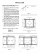
1. Mark the cutout area. (See figures 8 and 12 through 14
for dimensions.)
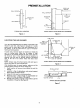
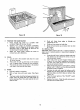
2. Drill holes at the corners of area to be cut out to
permit insertion of saw blade. (See figure 11.)
•_ Carefully saw out wall or ceiling area exactly as
marked. Remember the frame flange is only 3/4-inch
wide. It will not cover an oversize or irregular cutout.
4. Figures 12,13 and 14 show several possible situations
that will be apparent when the cutout is finished. With
standard stud spacing you will run into either one or
two studs. They must be cut and the section removed
at air cleaner location.
5. Install headers all around air cleaner opening (four
sides). This will provide good support of air cleaner and
restore the original wall strength. Use basic concepts
shown in figures 12 through 14 if your wall differs
from the diagrams shown.
NOTE: Thesame method for framing the air cleaner cutout
:_, be applied to ceiling joists, when a ceiling installation is
required.
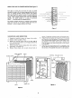
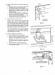
6. Cut out required opening in return-air duct. The duct
cutout should fit air cleaner cabinet as closely as
possible. If duct is more than six inches from wall
surfac'e, install a connecting duct between air cleaner
cabinet and existing duct. (See figures 5 and 6.)
7. Slide the frame assembly into the finished cutout.
Make sure it fits properly, then remove it.
*Dimension "'A'" in figures 12 through 14 are asfollows:
1000 CFM = 17'"
1400 CFM = 24""
2000 CFM = 29"
HOLES
CUT-OUT MARK
Figure 11
i i
T
A
J l
II
ADD STRINGERS AND HEADERS AT SHADED LOCATIONS
Figure 12
EXISTING STUDS
I__
TOE NAIL
ADD STRINGERS AND HEADER AT SHADED LOCATIONS
A
I EXISTING STUDS '
I/ t
! = EXISTING STUDS
I Is/
• TOE NAIL TOE NAIL
I
I
ADD STRINGERS AND HEADERS AT SHADED LOCATIONS
I
I
Figure 13
Figure 14