
Manual

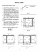

, Prepare air-cleaner cabinet for electrical connection as
follows:
a. Determine location of power supply source which
will dictate the location of electrical wiring.
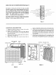
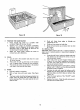
b. Three knockouts (figure 15) are located in upper
right-hand corner of cabinet. A built-in "J" type
junction box is included. Secure wiring with
accepted hardware.
c. The usual knockout location is at upper rear of
cabinet. If an obstruction, prohibits this location,
useeither of the two other knockouts.
d. Allow at least 10 inches of wire lengths on inside
of cabinet for connection to air-cleaner wires.
9. Connect air-cleaner to existing wiring.
Wiring to the air cleaner must comply with local
electrical codes. For this reason, specific wiring
instructions are not given. The color coding of wires
out of the female power receptacle are white and
black. They should be matched to wires of the same
color from electrical power source (figure 18). Connect
ground wire from power source directly to the green
grounding wire provided in the junction box area.
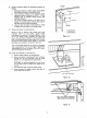
This Thru-the-Wall electronic air cleaner is equipped
with a solid state Air Flow monitor (figure 16) that will
automatically turn your air cleaner ON or OFF when-
ever the furnace fan is running.
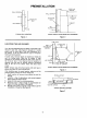
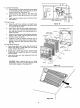
10. Install frame assembly in wall opening:
a. Slide air cleaner cabinet into wall opening.
b. Secure the cabinet in opening with nails, or screws,
through the 12 holes provided in face of flange
(figure 17), or through holes in cabinet walls.
C,
d.
CAUTION: On ceiling installations, be sure to use
all 12 flange holes to support full weight of air
cleaner.
If an extension duct is required, install it now.
Reach through air cleaner cabinet and tape all
joints made into ductwork.
4-13/16"
lJ KNOCKOUT
LOCATIONS
Figure 15
AIR FLOW MONITOR
Figure 16
NAILS (OR SCREWS) THROUGH
THESE HOLES (12 LOCATIONS}
Figure 17
==1
7