
user manual

2
PRINCIPLE OF OPERATION
When the temperature in the controlled area rises, the
fluid in the coiled bulb expands, causing the contacts in
the switch mechanism to snap closed, turning on the
ventilating fan to high speed.
As the area cools, the fluid contracts. When the tempera-
ture reaches the control setting, the contacts snap open,
fan reduces to slow speed. When area cools to low setting
contacts open stopping the fan.
INSTALLATION
The control may be mounted in any location provided that
the temperature and humidity of the air in which it is
located will not cause a condensation on the switch parts.
If the ventilating equipment manufacturer has made pro-
visions for, or recommendations for location of this con-
trol, then follow those instructions. If not, the following
suggestions should be observed:
1. The control should be mounted approximately six feet
from the floor, as near as possible to the centre of the
ventilated area.
2. Do not locate control on or near an outside wall.
3. Wherever possible, mount on a partitioning wall or on
a post.
4. Keep the control as far as possible from undesirable
sources of heat and cold, such as:
a. Windows or doors
b. Direct rays from sun
c. Steam hot water or cold water pipe
d. Adjoining outside walls.
5. Mount control in vertical position with coils facing
downward.
CAUTION
Do not twist or uncoil the coiled bulb on the
bottom of the control case. Do not attach conduit
through coiled element to bottom of control. In-
stead, run conduit to top of control.
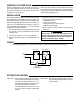
WIRING
All wiring should be done in accordance with local and national electrical codes and ordinances.
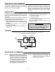
STEP ONE: Set Low Speed Selector at the tempera-
ture you want the Left Switch Fan to run on
low Speed. At approximately 3°F (1.7°C)
with differential adjusted to minimum posi-
tion below this setting Fan will stop.
Low Speed Selector must be set at least
5°F (2.7°C) below setting of High Speed
Selector.
STEP TWO: Set High Speed Selector at the tempera-
ture you want the Right Switch Fan to run
on High Speed.
SETTING THE CONTROL
2-SPEED MOTOR
HIGH
SPEED
LOW
SPEED
COMMON
LEFT SWITCH
RIGHT SWITCH
RED
BLUE
WHITE
HOT
N
LINE