LIST OF CONTENT: REGULATORY INFORMATION 1 INDUSTRY CANADA STATEMENT: 2 SAFETY INSTRUCTIONS 3 IMPORTANT INFORMATION TO INSTALLERS AND USERS 5 1 INTRODUCTION 6 2 OVERVIEW OF THE FLEETBROADBAND SYSTEM 8 3 MAIN UNITS 9 4 GETTING STARTED 14 5 USING THE PRIMARY HANDSET 19 6 USING THE WEB CONSOLE 55 7 TROUBLESHOOTING 114 FX 250 / FX 500 User Manual
REGULATORY INFORMATION FEDERAL COMMUNICATION COMMISSION NOTICE FCC Identifier: QY9-AVCFX500BDE / QY9-AVCFX250BDE USE CONDITIONS: This device complies with part 15 of the FCC Rules. Operation is subject to the following two Conditions: 1. This device may not cause harmful interference, and 2. This device must accept any interference received, including interference that may cause undesired operation.
INDUSTRY CANADA STATEMENT: IC: 5023A-AVCFX500BDE / IC: 5023A-AVCFX250BDE This device complies with Radio standard specification RSS -170 and RSS-210 of Industry Canada Rules. Operation is subject to the following two conditions: 1. This device may not cause harmful interference, and 2. This device must accept any interference received, including interference that may cause undesired operation.
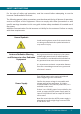
SAFETY INSTRUCTIONS For the sake of safety and protection, read the manual before attempting to use the Inmarsat FleetBroadband Terminal. The following general safety precautions must be observed during all phases of operation, service and repair of this equipment. Failure to comply with these precautions or with specific warnings elsewhere in this user guide violates safety standards of intended use of the system.
Grounding, cables and connections Service The chassis of the equipment must be connected to an electrical ground. This will minimise electric shock and mutual interference. In short, the terminal must be grounded to the vessel. Do not attempt to access to the interior of the terminal. Only qualified personnel authorized by its manufacturer may perform service. Failure to comply with this rule will result in the warranty void.
IMPORTANT INFORMATION TO INSTALLERS AND USERS General It is important that the user of this equipment read and observe all safety requirements and operate the system according to the descriptions published in this manual. Failure to comply may result in risk of injury or equipment failure and voids the validity of the warranty provided by equipment manufacturer. The system consists of 2 systems, BDU and ADU and must be used as provided by the manufacturer or authorized dealer.
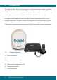
1 INTRODUCTION The Skipper FX 250 / 500 User Equipment (UE) is a dedicated compact solution specifically designed to meet the FleetBroadband ( FBB ) services for the maritime environment providing seamless ocean coverage from 76° North to 76° South. FBB is the marine version of the highly successful BGAN (Broadband Global Area Network) from Inmarsat. Through a maritime BGAN antenna, it provides constant, simultaneous access to voice and high-speed data in a compact solution.
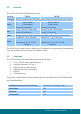
1.2 Features The FX 250 / 500 offers the following features: Services FX 250 FX 500 Coverage Voice, fax and data are available globally except for the extreme polar regions Voice 4kbps AMBE+2 3.1KHz Audio (above 20º elevation) 4kbps AMBE+2 3.1KHz Audio (above 5º elevation) Fax Group 3 fax via 3.1KHz Audio (above 20º elevation) Group 3 fax via 3.1KHz Audio. (above 5º elevation) SMS Standard 3G (up to 160 characters) per SMS. Maximum of 4 chained SMS.
2 Overview of the FleetBroadband system BGAN Services The Broadband Global Area Network (BGAN) is a global Satellite Internet Network using portable terminals. The terminals are usually connected to a laptop computer to access broadband Internet in remote locations, where a line-of-sight to the satellite exists. The user can make phone calls, access the Internet, check e-mail, download files, or perform any other Internet activity using the terminals.
3 Main Units The FX 250 / 500 FleetBroadband system include the following main units: ADU BDU Skipper FX 500 Class 8 FX 500 Skipper FX 250 Class 9 FX 250 Handset Skipper FX Primary Handset FX 250 • FX 250 FleetBroadband BDU • FX 250 FleetBroadband ADU • Primary Handset FX 500 • FX 500 FleetBroadband BDU • FX 500 FleetBroadband ADU • Primary Handset 3.1.1 Above Deck Unit (ADU), the antenna unit The FX series ADU is Maritime FleetBroadband 3-axis controlled antenna.
All signals (and DC power) shall pass through a single coaxial antenna cable, which connects the ADU to the BDU. 3.1.2 Below Deck Unit (BDU) The BDU has been developed for maximum flexibility and is the controlling unit for the FBB UE. It features a reliable industry standard interfacing field and enables users to have optimal connectivity no matter what the conditions or your position at sea.
Status LEDs There are 3 Status LEDs to indicate the operational status of the BDU at one glance. Each LED is assigned to the following function: • • • BDU Terminal Status ADU Status Registered to Network Status SIM Card Slot The BDU has a SIM (Subscriber Identity Module) card slot located at the connector panel behind a small cover plate. The UE requires a dedicated FBB SIM card to access the FBB network and configure the settings of the UE.
Front panel The following diagram shows the front panel of the BDU. 1 2 3 4 13 5 12 8 7 6 11 9 10 1. 2. 3. 4. 5. 6. 7. 8. 9. 10. 11. 12. 13.
3.1.3 Primary Handset The wired Primary Handset has a colour LCD and keypad for making and receiving voice calls and sending SMS using an interface similar with a mobile phone. It can serve as a remote access for user to access various BDU functions. The Primary Handset connector is plugged into the BDU primary handset port and it is powered directly from the BDU.
4 Getting Started 4.1.
4.1.2 Preparation for Operation 4.2.1 Install the SIM card. The system requires a SIM card to access the Inmarsat’s FleetBroadband network and configure the settings of the BDU. Please refer to your Airtime Service Provider for more information. 1. Tilt up the SIM card slot rubber cover as shown. Note: Make sure the BDU is switched off before inserting or removing the SIM card. 2. Position the SIM card with its goldcontacts facing down.
4. Tilt down the SIM card cover to its original position. 4.2.2 Connecting Primary Handset The Primary Handset is powered from the BDU through the Primary Handset Port 1. Plug in the Primary Handset connector into the Handset port on the BDU front panel. Make sure the key of the handset is aligned to the red mark of the handset port. 4.2.3 Connecting the Wi-Fi Antenna 1. 16 Connect the Wi-Fi antenna to the Wi-Fi’s connector on the BDU front panel.
4.2.4 Powering Up The System 1. Use the ON/OFF switch on the BDU’s front panel. 1. Wait for all LED indicators to turn green to indicate the system is completely power up. Refer the table below for meaning of the status indicators. LED Name TERMINAL ANTENNA REGISTERED Status Meaning Steady Amber BDU is powering up Steady Green BDU has powered up successfully. Steady Red BDU detects failure. Blinking Amber Switching OFF BDU Steady Amber ADU is powering up.
4.2.5 Entering your SIM PIN When you acquire the SIM card from the Airtime Service Provider, a PIN (Personal Identification Number: 4 to 8 digits) is provided together with it. Note: You will need to enter the PIN at start-up if the FBB BDU has been powered down. Follow these steps to enter the SIM PIN: Using the keypad on the Primary Handset, enter the SIM PIN. Press to confirm the SIM PIN.
5 USING THE PRIMARY HANDSET 5.1 The Primary Handset The Primary Handset is connected to the FBB UE using the dedicated HANDSET port and is powered directly from the BDU. Equipped with a large 2’, 65K CSTN, 220 Liquid Crystal Display (LCD), Primary Handset not only acts as a standard phone that allows you to make/ receive voice calls, it also serves as a remote access UE (User Equipment) for you to access various configurations supported by the BDU.
5.2 Powering Up the Primary Handset The Primary Handset is automatically powered up once it is connected to the dedicated HANDSET port. Depending on the conditions of the BDU, the Primary Handset may start in the following modes: 5.2.1 Full functioning mode In full functioning mode, there is no PIN authentication required to start using the FBB system. All BDU settings including contacts, messages and call logs are loaded into local memory of the Primary Handset once the BDU is configured.
5.3 Primary Handset 1 2 3 4 5 6 7 9 8 10 11 12 13 14 1. 2. 3. 4. 5. 6. 7. 8. 9. 10. 11. 12. 13. 14. 15. Earpiece Display Ear-set Jack OK Key 4-Way Navigation Keys Select Left Key Select Right Key Call/Send key End key Keypad (Alpha-numeric) Mode Key Clear Key Microphone Service Port Ringer* *The ringer is located at the back of the Primary Handset.
5.3.1 Keypad - Description and Functions Keys Description/Functions 4-way navigation ring. Press the 4-way navigation ring to scroll left, right, up, and down on the display. Enables scrolling through names, phone numbers, menus or settings. OK key. Pressing this key selects/confirms the function highlighted on the display. Left selection key. The function of this key depends on the guiding text shown on the display above the key. Right selection key.
Keys Description/Functions Star * key When entering a phone number, press this key to insert a *. Press and hold this key to insert a +. When writing text, press this key to access a list of special symbols. Hash # key When entering a phone number, press this key to insert a #. To quickly change the text input method when writing text, press this key repeatedly and check the indicator at the top of the display In standby mode, press and hold this key to set the Primary Handset into silent mode.
5.3.2 The Main Display Screen BDU Status Indicator Line Satellite Signal Strength Primary Handset Status Indicator Line Selection Key Line • BDU Status Indicator line The indicator line shows status symbol informing you about the operating conditions of the BDU. • Satellite The indicator line shows status symbol informing you about the satellite service. • Handset Status Indicator line The indicator line shows status symbols informing you about the operating conditions of the Primary Handset.
Primary Handset Status Indicators Table below explains the meaning of each status indicator displayed in the Main Display screen. Status Indicator Description New short message (SMS) in inbox. Available CS domain services. Available PS domain services.
5.3.3 Primary Handset Operations Making a Voice Call Before making a voice call, please make sure that: -The Primary Handset is connected to the BDU ( status indicator should be on) -The Primary Handset is NOT radio silent ( status indicator should be off) -The BDU has successfully registered with the network and ready for CS domain (voice) services ( status indicator should be on) You can use the following two options for making a call: • Manual Dial: 1.
Adjusting volume during a call Use the 4-way navigation ring to adjust the volume.
Using the Menus You can access the Menu System by pressing the Right Display screen. selection key in the Main The main menu of the Primary Handset includes nine (9) menu options with each menu option having their respective sub-menus. You can use the 4-way navigation ring to navigate to the desired menu option and press to confirm your selection. You can also end the menu or sub menus and return to the Main Display screen at any time by pressing the key.
Contacts Menu The Contacts menu allows you to store, retrieve and update names and phone numbers of your contacts in the Primary Handset memory and in the SIM card memory. You can also access this menu by pressing Left selection key in Main Display screen. This menu lists all the contacts saved in both the BDU and SIM card memory where, Indicates contacts that are saved in BDU and Indicates contacts that are saved in SIM card.
Note: Refer to “Tips for writing the text” section under New message for more information on text writing. • Search Select this to enter a specific name to search within the contact list. • Delete Delete selected contact. Note: You can also delete the selected contact by pressing the Clear key. • Copy Select this to copy the selected contact from SIM card memory to BDU memory or vice versa. • View number Display the number of the selected contact.
• Forward contact Forward information of this contact using SMS. • Assign Speed Dial Add this contact to the speed dial list. Note: You can also make a voice call to the selected contact when browsing through or viewing the contacts by pressing the Call key.
Note: This option is not available when the log entry already has an entry in the contact list. Note: You can also make a voice call to the number of the selected log entry when browsing through or viewing the call log by pressing the Call key. Clear call lists Select this to clear the call log entries. Available log options are: • • • • Missed calls Received calls Dialled calls All calls Delete all logs including Missed, Received and Dialled logs.
Telephony Menu The Telephony menu allows you to configure telephony related settings with the following sub menus: Port Settings • Primary Handset Contain options for incoming and outgoing call types. Select this to configure the call type settings. The following options are available when pressing the Left selection key while browsing through the list: Ø Standard Ø NONE • Phone Port Contain options for incoming and outgoing call types. Select this to configure the call type settings.
Speed dial • Setting Contain options to enable/disable the speed dial feature • Speed Dial List Select this to configure the speed dial list. The following options are available when pressing the Left selection key while browsing through the list: • Assign Assign a contact to the selected entry. To assign a contact: 1. 2. Select Speed Dial List. Browse through the list to locate an empty entry. 3. Select Options by pressing Left 4. Select Assign and press 5.
Data Menu The Data menu provides the following sub menus to manage and configure data connections (PDP profiles) for the BDU: Manage profiles Allow you to manage the Primary and Secondary PDP profiles. • Primary profiles One Standard Primary PDP profile has been created in the Primary profile list as a default profile.
Ø Adding/Editing profiles You can press the Left existing profile settings. selection or key from the option list to add new or edit • Profile name Specify the name of the profile. • Connection type Both Standard and Streaming connection types are supported. • APN Specify information of the APN (Access Point Name). Further available settings are: APN: Specify the Access Point Name for the connection. Default APN is according to SIM card.
Note: For 32k, 64k and 128k Streaming profiles, there are three additional options when selecting editing their settings. The additional options are: • Desired rate Choose the desired rate for the different profiles. Note that the default setting for each profile is the profile chosen. For example, for 32k Streaming, the de fault rate is 32k. • Minimum rate Choose the minimum rate for the different profiles. Note that the default setting for each profile is the profile chosen.
Note: You will be prompted to save the changed settings before exiting the sub menu. Press Left selection key or key to save the changes. Icon in the profile list indicates that the profile is not active and icon the profile is currently active in use. indicates that Status Allow you to check the status of the data connection. You can also activate / de-active a specific profile in the status display list.
To de-active a primary data connection when there is an active connection: 1. From the data status list, select Options using the Left 2. Select Deactivate using Left selection key or selection key. key. 3. You are prompted to confirm de-activation. Confirm de-activation by selecting Yes using the Left selection key or key.
• Save Select this to save the message into the draft folder. • Clear screen Select this to clear all the written text. Tips for writing the text: • • Press the 0 key to add a space.
` Inbox Contain new/opened text messages that you have received. When browsing through the messages list using the 4-way navigation ring, Indicates an unread (new) message and Indicates read (opened) text messages. The following are available options when pressing the Left browsing through or viewing the messages in this folder: • selection key while Open Open selected message.
Sent Contain text messages that you have sent. The following are available options when pressing the Left selection key while browsing through or viewing the messages in this folder: • Open Open selected message. You can also press while browsing through the message list to open the selected message (This option is not available when viewing the message). • Delete Delete selected message.
• Send Send this message to another recipient. • Save Save the selected message into the Draft folder • Add to contact Select this to add the phone number of the selected message into the contact list. Note: You can also make a voice call to the selected message contact when browsing through the message list by pressing the Call key. Options The following settings are available in this sub menu: • Message Centre Select this to set the number of the SMS service centre.
Settings Menu The Settings menu provides the following sub menus to configure the BDU: Ciphering mode Contain options to enable/disable the use of ciphering mode between the network and BDU. Note: Status icon is displayed in the Main Display screen when ciphering is enabled. Ethernet Allow you to configure settings related to Ethernet connection. • Transceiver IP Address Specify the IP address of the BDU. The default IP address of the BDU is 192.168.1.
q Lease time Display the lease time. Default lease time is 60. Except for DHCP server, the rest of the display settings can be edited by pressing the Left selection or keys. Note: Make sure that the format is correct when entering an IP address. Press the Star multiple times to insert the “.” sign. key Satellite Manage settings related to Inmarsat satellites. • Satellite selection Allow you to select the preferred satellite to lock on to.
Allow you to configure for call forwarding services depending on various conditions. The following forwarding conditions are available for configurations: q All Calls All calls are unconditionally forwarded. q Busy Calls are forwarded when the BDU is busy. q No answer Calls are forwarded when no answer from the BDU for a specific time. q Not reachable Calls are forwarded when BDU is not reachable.
• Retrieve Retrieve network settings of the selected condition. • Update Update configured settings to the network for the selected condition. Note: Always use Retrieve all or Retrieve options to retrieve the latest settings from the network. Use Update all or Update options to update the network settings after configurations. • Call barring Allow you to configure for call barring services depending on various barring condi tions.
• Call waiting Contain options to enable/disable call waiting services. You can also press the Left • selection key for the following options: Retrieve Retrieve network settings of the call waiting service • Update Update configured settings to the network Note: Always use Retrieve option to retrieve the latest settings from the network. Use Update option to update the network settings after configurations.
Terminal Menu The Transceiver menu provides the following sub menus to check for information and perform resets on the BDU: Signal strength Show graphical representation of current signal strength and GPS type. Table below describes the available GPS type icons used in this sub menu: This icon shows that the BDU is in the process of acquiring a GPS fix when there is no previously stored GPS fix. This icon shows that the BDU is using New GPS coordinates.
v Serial number Serial number of the BDU Antenna Unit Info Display a list of information of the Antenna. v Serial number Serial number of the Antenna Transceiver restart Soft restarting the BDU Limited reset Perform limited reset on the BDU. Apart from full factory reset that is not available in Primary Handset, limited reset only resets a small portion of the BDU settings. Stored GPS status, contacts, call logs and event logs are not cleared during limited reset.
Security settings Menu The Security Settings menu provides the following sub menus to configure the security settings of the BDU using different PIN: Terminal PIN SIM PIN There are three options available for selection under each sub menus to manage the PIN and security settings for the BDU: ο Enable Enable the selected PIN.
ο Change Change the PIN to a new one. You will be asked to key in the existing PIN (or default PIN if it has not been changed) before the PIN can be changed. Note: PIN has to be enabled before it can be changed.
Phone manager Menu The Phone manager menu provides the following sub menus to configure settings that are local to the Primary Handset: Display Configure settings that are related to Primary Handset display. • Backlight To set the duration of the display backlight to remain on. Settings range from Always On (Backlight permanently turned on), 15 seconds to 1 minute. Note: The backlight will be slightly dimmer and finally off when there is no keypad activity after sometime.
• Ring tone • Tone Select desired ring tone pattern. • Volume Configure the volume of the ring tone. Using the 4-way navigation ring , press up/right to increase and down/left to decrease the volume. Language Allow you to change the menu display language. Factory settings Allow you to configure default factory settings of the Primary Handset.
6 USING THE WEB CONSOLE 6.1 Register to the Network 1. Connect your computer to the FBB BDU using a LAN cable. 2. When the connection has been established, open the web browser. 3. Type http://192.168.1.35 in the Address field and press Enter. 4. When the Login screen appear, type in admin in the Username field and 1234 in the password field. Click Login. 5. Click the Login button.
The FBB BDU Web Console will appear on your screen. The FBB BDU will automatically register to the network. This process will include GPS acquisition, satellite tracking and registration with the network, which will take a few minutes. Once the process is completed, you will see the following message appearing at the bottom line of the Web Console. “Registered to Network but no active data connection exists. You are now able to make phone calls and send SMS.
6.2 Navigating the Web Console 6.2.1. Menu Overview Below you can see all of the sub menu tabs, under each icon menu item. Setup Phone SMS Data Settings Terminal Info Phonebook Compose Connection Language Satellite Selection Call History Inbox Primary Profiles Terminal Info Sent Port Forwarding Ethernet Draft Firewall Telephony PPPoE PIN Settings SMS Tracking Admin Support Accounts 6.2.2. Status/Action Indicators These icons indicate the status of the FBB BDU.
Status Icons Status Indicator Description Circuit Switch Icon Indicates the Circuit Switch service status (Voice calls, SMS, FAX). Packet Switch Icon Indicates the Packet Switch service status (Internet : Indicates the Packet Switch service status (Internet Browsing, FTP, email). GPS icon Indicates if a new GPS fix is available or not. These icons indicate the status of the FBB BDU and also function as shortcut buttons to the respective menu as indicated below. • Orange indicates the item is active.
6.3 Navigating the Web Console Setup Menu Viewing Terminal Information 1. Click on Setup icon. 2. Click Terminal Info. The terminal information tab shows Signal strength, Temperature, GPS Status, Elevation angle and Registration status.
Satellite Selection The default Satellite Selection is in Auto mode. In Auto mode, the UE will scan all the visible satellites and track the satellite with the most optimum elevation angle or the last used satellite. Note: Changing the satellite selection will terminate any existing active voice/fax call or data connections. Follow these steps to change your satellite selection: 1. Click on Setup icon 2. Click the Satellite Selection to view the visible satellites.
Phone Menu 1. Click on Phone icon. Phone menu provide the following options: I. • • • PhoneBook The Phonebook entries can be stored on the SIM card or the FBB BDU. Allows you to view, add, edit and delete entries on your Phonebook list. You can make and send SMS messages directly from your Phonebook entries. View option The View option allows you to view the Phonebook entries from the different storage locations.
Storage Usage Shows the number for Phonebook entries used in the SIM card and TU locations. For example: (SIM –2/150) indicates: Storage location – SIM card Total number of entries used = 2 Total number of entries available = 150 Adding a new Phonebook entry 1. Click Add. 2. Enter the Name and Phone number. 3. Select the storage location and click Save. Editing a Phonebook entry 1. Select the entry from the Phonebook list. 2. Click Edit. 3. Proceed to change the Name and/or Phone number.
Sending SMS from the Phonebook Follow these steps to send SMS from the Phonebook: 1. Select the entry from the Phonebook list. 2. Click Send SMS. 3. The Phonebook console switches over to the Compose SMS console. 4. Type in the text message and click Send. II. Call History To check history log of calls made and received.
View option The View option allows you to view the Call History entries. From the drop-down menu, select: All To view the list of the dialed, received and missed calls. Dialed Call To view the list of dialed calls only. Received Call To view the list of received calls only. Missed Call To view the list of missed calls only. Sending SMS from the Call History list Follow these steps to send SMS from the Call History list: 1. Select the entry from the list. 2. Click Send SMS. 3.
Deleting a Call History entry Follow these steps to delete a Call History entry: 1. Select the entry from the Call History list. 2. Click Delete. 3. Click Ok to confirm or click Cancel to abort deleting the entry. 4. Click Refresh to refresh the Call History list.
SMS Menu 1. Click on SMS icon. SMS menu provide the following options: I. Compose To compose and send text messages. Simply enter a mobile number, type your message and click Send. II. Inbox Shows the details (Sender information, Message, Date and Time stamp) of all SMS received. III. Sent Shows the details (Receiver information, Message, Date and Time stamp) of all SMS sent. IV. Draft Stores unsent messages for retrieval later.
I. Compose Composing a New Message Follow these steps to compose a new SMS: 1. Enter the receiver’s phone number in the Phone no. field or click the Phonebook icon if the receiver’s number is listed in the Phonebook. 2. Type the message in the text editor box. Note: Message is limited to 160 characters (using 7 bit encoded default alphabets) including spaces between words.
II. Inbox Shows the details (Sender information, Message, Date and Time stamp) of all SMS received. Replying to a SMS Follow these steps to reply a SMS: 1. Click on a SMS to select it. The selected SMS will be highlighted in light blue. 2. Click Reply. 3. Click OK to reply with the original contents or Cancel to reply without the original content. The Inbox console switches over to the Compose console. 4. Enter your reply in the text editor. 5. Click Send to send your reply SMS.
Forwarding an SMS Follow these steps to forward an SMS: 1. Click on a SMS to select it. The selected SMS will be highlighted in light blue. Click Forward. 2. The Inbox console switches over to the Compose console. Enter the receiver’s number in the Phone No. field. 3. 4. Click Send to forward the SMS. The SMS will be sent to the recipient. Deleting a single SMS from the Inbox list Follow these steps to delete a single SMS from the Inbox list: 1.
III. Sent Shows the details (Receiver information, Message, Date and Time stamp) of all SMS sent. Resending a sent SMS Follow these steps to resend a sent SMS (sending the same SMS to the same receiver): 1. Click on a SMS to select it. 2. Click Resend. 70 3. The SMS will be sent to the recipient.
Forwarding a sent SMS Follow these steps to forward a sent SMS to another recipient: 1. Click on a SMS to select it. Click Forward. 2. 3. The Sent console switches over to the Compose console. Enter the receiver’s number in the Phone No. field. 4. 5. Click Send. The SMS will be sent to the recipient. Deleting a SMS from the Sent list Follow these steps to delete a single SMS from the Sent list: 1. Click on a SMS to select it. 2. Click Delete. 3.
Deleting multiple SMS from the Sent list Follow these steps to delete multiple SMS from the from the Sent list: 1. Select the message by checking the checkboxes beside each SMS. 2. Click Delete. 3. Click OK to confirm the delete, or Cancel to abort the delete. 4. IV. Click Refresh to refresh the Sent list. Draft Stores SMS saved from the Compose console. Follow these steps to send a draft SMS: 1. 2. 72 Click on a SMS to select it. Click Send.
Forwarding a draft SMS to another recipient Follow these steps to forward a draft SMS to another recipient: 1. 2. Click on a SMS to select it. Click Forward. The Draft console switches over to the Compose console. 3. Enter the receiver’s number in the Phone No. Field. 4. Click Send to forward the SMS. The SMS will be forwarded to the recipient. Deleting a SMS from the Draft list Follow these steps to delete a SMS from the Draft list: 1. 2. 3. Click on a SMS to select it.
Deleting multiple SMS from the Draft list Follow these steps to delete multiple SMS from the Draft list: 1. 2. 3. 4. Select the message by checking the checkboxes beside each SMS. Click Delete. Click OK to confirm the delete, or Cancel to abort the delete. Click Refresh to refresh the Draft list. Data Menu 1. Click on Data icon. Data menu provides the following options: I. II. III. IV. V. VI. VII. I.
When connected, APN and the assigned public IP Address details will be displayed. You can proceed to access the Internet and use the related features. 3. To disconnect the data connection, click Disconnect. The PDP context will be deactivated.
II. Primary Profiles Primary profiles define the connection type. You can select from a list of profiles to be the default primary profile and connection type. From Profile 7 to Profile 10, you can create your own customized primary profile. Note: The Standard profile is set as the default primary profile and the default connection type is standard (this is charged by the volume [in kilobytes] of data used). Profile Name Change the profile name as desired. Connection Type Change the type of connection.
Access Point Name (APN) By default, the APN from the SIM will be selected. Follow these steps to change the Access Point Name (APN): 1. Select User Defined. 2. Enter the new APN in the field space provided (e.g. BGAN inmarsat.com). 3. Enter the username and password if required. IP Configuration By default, the Dynamic IP Address is selected. Follow these steps to use Static IP Address: 1. Select Static IP Address and enter the IP Address in the space provided. 2.
IV. Port Forwarding Port Forwarding is a feature for Router (multiple-user) mode. This feature sets the FBB BDU to direct incoming traffic on certain TCP/UDP port to a specific port on a local PC (IP Address). Follow these steps to add a new forwarding rule: 1. Click the Add button. 2. Enter the Incoming Port number in the space provided. (For example, the user expecting HTTP traffic, the port is 80).
3. Enter the Destination IP Address. (For example, the IP Address of the PC that is connected to the FBB BDU). 4. Select the Protocol type TCP (e.g. for HTTP, it will be TCP) UDP. 5. Enter the Destination Port number in the space provided (For example: listening port of the particular service (for example TCP port 80 for web server) on the PC that is connected to the FBB BDU). 6. Click Apply to allow the settings to take effect. V. Firewall By default, the Firewall is disabled.
3. Once the Firewall service is activated, a pop-up message box indicates the Fire wall service is activated and requires rebooting of terminal for the service to take effect.
Enable Firewall Settings 1. Navigate to Data>Firewall>Setup to enable Firewall protection. 2. Select Enable. 3. Click Update. Incoming Rule To add and define up to 10 rules to allow or reject incoming packets.
Outgoing Rule To add and define up to 10 rules to allow or reject outgoing packets.
DoS Protection To add to enable block packets from public network. By default, the DoS is disabled.
Port Scan Protection To enable block other packets from public network. By default, the Port Scan Protection is disabled. Service Filtering To prevent external network accessing your terminal. By default, the Service Filtering is disabled.
Administrator Control To block any keyword in the content of the accessing page.
VI. PPPoE By default, the PPPoE is disabled. 1. 2. 3. Select Enable. Click Update. Once the PPPoE service is enabled, a pop-up message box indicates the PPPoE service is activated and requires rebooting of terminal for the service to take effect VII. Setting You can select the Ethernet mode to be used for data connection. Follow these steps to select the Ethernet mode: 1.
Settings Menu 1. Click on Settings icon. Setting menu provides the following options: I. II. III. IV. V. VI. VII. VIII. IX. X. XI. XII. I. Language Terminal Info Ethernet Telephony PIN SMS Wi-Fi Tracking Admin Support Accounts About Language Select the desired language for the Web Console to be displayed. (Spanish, Chinese-Simplified and Chinese-Traditional may not be an option that is available at the time of purchase).
II. Terminal Info This tab shows general information about the UE, Error/Event Logs and Call Logs. Information Displays information about the Manufacture ID, Software version, Model ID, IMEI number, IMSI number (only when a SIM card is inserted), Subscriber number and Antenna Unit’s serial number. Logs Displays event and error logs of the UE.
Call Log Displays the call history including standard voice calls, high-quality/fax calls, standard data sessions and streaming data sessions. Call Log Displays the total call usage and total data usage. Click clear to reset counter. III. Ethernet 1. 2. Click Ethernet to view and edit the Ethernet settings. Click Update to allow the settings to take effect. DHCP 1. 2. Click DHCP to view and edit the DHCP settings. Click Update to allow the settings to take effect.
Mac Address Filtering 1. 2. Click Mac Filtering to view and edit the Mac Filtering settings. Click Update to allow the settings to take effect. Reject List All PCs/Laptops will be allowed to access the TU except for those (MAC addresses) listed in the Reject List. Allow List All PCs/Laptops will be denied access to the TU except for those (MAC addresses) listed in the Allow List. When selecting this list, at least one entry should be there to access the TU.
IV. Telephony Interface 1. Select European Caller Line ID Phone connected or US Caller Line ID Phone connected from the Telephone Interface Configuration drop-down menu. Click Update to allow the setting to take effect. 2. Port Configuration For each of the 3 ports, a choice of the quality calls can be selected. Select your ideal call quality and click Update.
Fax Port For the fax port, if no subscription is made, there will be no choices. If fax subscription is made, 3.1KHz high quality fax call will be available. Caller ID 1. Click Retrieve to get current setting of the Allow called party to see your number configuration. 2. To change the setting, select Yes, No, or According to network subscription for the Allow called party to see your number configuration. 3. Click Apply to allow the setting to take effect.
Call Waiting 1. Click Retrieve to get current setting of the Enable call-waiting configuration. 2. To change the setting, select Yes or No for the Enable call waiting configuration. Click Apply to allow the new setting to take effect. 3.
Call Barring 1. Click any individual Retrieve option to get the current setting of the corresponding scenario in which the calls would be barred. 2. Select the scenario in which the calls would be barred, or deselect the scenario to disable the corresponding call barring. 3. In the Barring PIN field, input a PIN for call barring setup. 4. Click Apply to allow the corresponding setting to take effect. 5.
Call forwarding 1. Click any individual Retrieve option to get current setting of the cor responding scenario in which incoming calls would be forwarded. 2. Select the scenario in which the calls should be forwarded, or deselect the scenario to disable the corresponding call forwarding setting. 3. In the Divert to Number field, input the phone number where the incoming calls should be forwarded to (+). 4.
Call Restriction The Call Restriction is only enabled for outgoing call. There are 2 types of restriction: 1. Phonebook – The user is only able to make outgoing calls from the phonebook list. 2. Call List – In this segment, it further categorised into Allowed List and Blocked List for the 3 types of telephony functions. a. Allowed List – The administrator can either enter the telephone numbers or simply the country and/or area code to limit other users to make out going calls.
V. Pin Terminal PIN 1. 2. 3. 4. Click Transceiver PIN to configure the Transceiver PIN settings. Select Disabled if you do not need to set the Transceiver PIN. Select Enabled to set the Transceiver PIN. Enter the PIN number in the Enter PIN filed and click Update PIN. Follow these steps to change the Transceiver PIN: 1. Enter the old PIN number in the Enter Old PIN field. 2. Enter the new PIN number in the Enter New PIN field. 3.
SIM PIN2 1. 2. 3. 4. Follow these steps to change the PIN Password: 1. 2. 3. 4. 5. Note: The SIM PIN2 depends on the SIM card. Consult your equipment distributor if necessary. 98 Click SIM PIN2 to configure the SIM PIN2 settings. Select Disabled if you do not need to set the SIM PIN2. Select Enabled to set the SIM PIN2. Enter the PIN number in the space provided and click Update PIN. Enter the old PIN number in the Enter Old PIN field.
VI. SMS To change the SMS service Center Address number, enter the new number in the space provided and click Update. Note: Please contact your distributor or service provider if you do not know the Service Center Address. VII. Wi-Fi By default, the Wi-Fi is disabled. Setup 1. Select Enabled to turn on the Wi-Fi module. (Go to Wireless Setting to enable Wi-Fi to be accessible by other devices.) Click Update. 2. 3.
System info Shows you software version and MAC address. Wireless Settings 1. Select Enabled to allow the WI-Fi network access to Wi-Fi enabled devices. 2. Choose ideal network mode, channel bandwidth and channel. 3. If required, Network Name can be renamed by user.
Security Settings Follow the steps to configure the security settings of the Wi-Fi module. 1. Select the security mode and authentication key. Note: There are four sets of security passwords available for your security configuration and you can only select one set of password. 2. Select the default key to enable the desire password from Key 1 to Key 4 respectively.
VIII. Tracking Settings 1. 2. 3. 4. 5. 6. 7. 8. 9. 10. 11. 12. Select Disabled if you do not need GPS reporting. Select Enabled if you need GPS reporting. Select either IP Data or SMS mode. Key in the desire frequency in seconds. (The time interval to update the server). Key in the server phone number (SMS mode only). Key in the server IP address (IP Data mode only).
5. 6. Select the type of Geo Fence: a) Circle (1 points, radius) b) Rectangle (2 points) c) Polygon (minimum 3 points. maximum 10 points) Key in the Latitude and Longitude values. Click Apply to confirm. APN (Access Point Name) This APN is configured to channel the tracking data traffic unlike the APN defined under DATA> Primary profile which is used for user data traffic such as Web browsing, FTP, Email etc.
IX. Admin Change Password Follow these steps to change the Web Console login Password: 1. Enter the old password in the Old Password field. 2. Enter the new password in the New Password field. 3. Re-enter the new password in the Re-type Password field. 4. Click Update. 5. The Web Console login password is now changed. Firmware Upgrade Firmware upgrade is to update your FBB BDU with the latest firmware. Please refer to your respective distributor for your firmware download.
1. Download or acquire the new firmware from your respective distribu tor and save it in your computer’s hard drive. Note: Make sure the FBB BDU is switched on and connected to the desktop/laptop computer using the LAN cable. 2. Select Firmware Upgrade. Read the Disclaimer message carefully before proceeding with the Firmware Upgrade. 3. Click Firmware Upgrade. The FBB BDU will reboot into Safe mode.
4. 5. 6. Browse to the location of the new firmware, select, and click Upload. Firmware upgrade will take approximately 10 to 12 minutes to complete. You will be prompted with the Result: Firmware Upgrade Completed message. Click Reboot Terminal to reboot the FBB BDU. 106 1.
Reboot Terminal If you wish to reboot the FBB BDU, click Reboot Terminal. Click Reboot and wait for a few minutes to allow the TU to reboot. Refresh your browser to update the Web Console page after reboot. Factory Reset To perform a Factory Reset, enter the Security code 0000 and click Factory Reset. Warning: All the settings and user data (e.g., Phone Book, GPS, etc.) of the FBB BDU will be cleared and reset to the default settings.
Save Settings To power down the FBB BDU Terminal Unit using the main power switch, it is recommended to save the recent setting changes. To save the recent changes, click Save Now. GPS Output By default, FBB BDU Transceiver Unit outputs the GPS data in NMEA format (at 9600bps) via the NMEA 0183 Connector for GPS output. For technician who wants to diagnose the system, he/she may collect the debug log messages by selecting Output Debug Log.
Ciphering Enabling the Ciphering option will make the FBB BDU to exchange voice and data in secure mode by encrypting them over the air. To enable/disable the Ciphering, select the option Enabled or Disabled respectively and click Update to make the change to take effect. Remote access By enabling the Remote Access option, user can remotely (from shore) access the terminal’s web console via internet.
To access the web console remotely, the user has to use the public IP address of the PDP context. Backup/Restore If you wish to backup your current settings, you may choose Full backup or Partial Backup: 1. Full backup – This apply only on the same terminal and not for distribution. 2. Partial backup – It allows distribution of certain settings to many terminals of the same Model and Firmware version.
Feature Displays the Optional Feature for Fax enabled. To activate the Fax feature, activation PIN is required. Please contact your DP for assistance.
Web This tab allows user to configure the web access. HTTP For remote access of web console, the user can configure the port number different from the default Port number: 80 if user wants to host a web server on the PC attached to the UT. HTTP Redirect When enabled is selected, a warning message will prompt user to activate PDP connection before web browsing.
X. Support Display information of the support telephone number, support email address, Support URL and Services URL. (The information shown is for sample purpose only.) XI. Accounts Select Add to add new user. 1. Select Delete to delete specific user. 2. Select Change Password to change specific user’s password.
7 Troubleshooting General LED status BDU LED LED behavior Descriptions / Remedial Actions Off BDU is in power-off state. Steady amber BDU is powering up. Steady green BDU successfully powered up. Steady red System failure during boot up or operation. User action required. Antenna LED LED behavior Descriptions / Remedial Actions Off ADU status is unknown. Steady amber ADU is powering up. Blinking amber ADU is calibrating. Blinking green System is searching for satellite.
SIM Card Symptoms SIM Card cannot be detected by BDU Descriptions / Remedial Actions • • • BDU indicates • “Wrong SIM Card” Ensure that a correct Inmarsat SIM card is used. Ensure that a SIM card is properly inserted into SIM Card slot. Retry by re-inserting the SIM card into SIM Card Slot before powering up the BDU. Ensure that a correct SIM card is used.
RJ11 Phone Port for Standard Call Symptoms Descriptions / Remedial Actions • Make sure that there is dial tone before making the call. For the case of busy tone, o Ensure that the line is not engaged by any other telephone services. o Ensure that all other telephony devices are hung up properly. Unable to make outgoing call For the case of no dial tone, o Ensure that the phone line is connected to the phone port of the BDU. Unable to receive incoming call • Hang up and retry the call again.
Primary Handset Symptoms Descriptions / Remedial Actions • No display / • power for Primary handset Check the DC power supply input to the BDU. Check the primary handset is properly inserted to the handset port. Unable to connect • to the BDU Ensure the primary handset is inserted to the handset port. Unable to make outgoing call Unable to receive incoming call • • • Ensure a correct number format is being dialed. Ensure proper BDU LED states. Hang up and retry to make the call.
Web page does not seem to be updated or there are unexpected errors occurred. • • Refresh the web page. Update the web browser to the latest version and retry. Data Connection Symptoms Unable to active Primary PDP context Unable to access internet after successfully Primary PDP context activation “Always On” feature is not working Descriptions / Remedial Actions • • • • • Ensure you are using a valid APN. Ensure that the signal strength is good. Ensure that the PS status icon is highlighted.
Antenna / Satellite Signal Level Symptoms Descriptions / Remedial Actions • • Low Signal Strength • • Check any obstruction such as the hull or monkey bridge of the vessel that may block the ADU’s line of sight. Check any interference signal from other electronics devices that are close to the ADU Check to ensure that the antenna cable is properly secured.