
Specifications

OPERATION
10
OPERATION
A bench grinder is designed for hand grinding
operations such as sharpening chisels, screwdrivers,
drill bits, removing excess metal, and smoothing
metal surfaces.
A Medium Grain Abrasive Grinding Wheel is suitable
for rough grinding where a considerable amount of
metal must be removed or when obtaining a smooth
finish is not important.
A Fine Grain Abrasive Grinding Wheel should be
used for sharpening tools or grinding to close size
tolerances because it removes metal more gradually
for precision grinding and gives work a smooth finish.
A wire brush is suitable for removing rust, burrs, etc.
from surfaces when a smooth finish is not important.
A variety of wire brushes are available for many
applications.
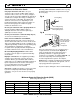
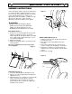
LIGHT (Figure 6)
1. This light provides focused lighting on the
workpiece when the grinder is operating at normal
operating speed.
2. The 12V bulb automatically turns "ON" as the
RPMs of the motor reach normal operating speed.
3. Use only automotive, 12V, single-contact bayonet
bulbs (3) when replacing. Position the lamp (1) as
desired.
4. Rotate the shade (2) for better illumination. To
change the light bulb, see page 11.
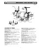
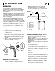
MOUNTING THE GRINDER (Figure 7)
1. To prevent the grinder from moving during
operation, it should be securely mounted to a
work surface or grinder stand.
2. Align the mounting holes on the grinder with
predrilled holes in a bench or grinder stand.
3. Insert bolts through the holes and tighten, using
washers, and nuts (not included) as shown in Fig. 7.
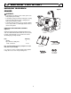
CHANGING THE GRINDING WHEEL (Figure 8)
1. Turn the grinder "OFF", unplug the electrical cord.
2. Remove the wheel guard and cover, using a
Phillips screwdriver.
3. With an adjustable wrench, loosen the tool rest hex
bolts. Slide the tool rest forward, away from the
grinding wheel.
4. Stabilize the wheel by holding the opposite wheel
firmly.
5. Remove the locking nut (2) and flange (3) from
the wheel being replaced.
Note: Turn the locking nut on the right-hand wheel
counterclockwise to loosen. Turn the locking nut on the left-
hand wheel clockwise to loosen.
6. Remove the old wheel (1) and replace with a new
wheel.
Note: Make sure the inner flange, outer flange and locking
nut are clean.
Note: Be sure to visually inspect the new wheel for cracks,
chips or other possible damage during shipping. Never use a
damaged wheel.
7. Hold the opposite wheel firmly and re-assemble
the flanges and nut onto the wheel arbor.
8. Tighten the locking nut just enough to hold the
wheel firmly.
Note: Do not overtighten. This could damage the grinding
wheel.
9. Reattach the wheel guard and cover.
4 1/2"
5 3/4"
2
3
1
4
5
6
7
8
9
3
2
1
1. Grinder base
2. Bolt
3. Flat washer
4. Rubber washer
5. Work surface
6. Flat washer
7. Lock washer
8. Hex nut
9. Jam nut
Figure 7
Figure 6