Operating Instructions — Parts Manual 20-Inch x 20-Inch Semi Automatic Horizontal Cut-Off Band Saw Model: 7060 WHM TOOL GROUP 2420 Vantage Drive Elgin, Illinois 60124 Ph.: 800-274-6848 www.wmhtoolgroup.com Part No.
Table of Contents Cover Page ........................................................................................................................... 1 General Specifications .......................................................................................................... 4 Operating Precautions .......................................................................................................... 5 Operating Instructions .......................................................................
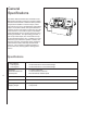
General Specifications The Wilton 7060 Semi-Automatic Horizontal Cut-Off Band Saw incorporates a number of exclusive design features and innovations to make this saw a powerful and productive addition to machine shops, maintenance shops, tool rooms, and fabrication and welding shops. The exclusive swivel control panel allows the operator access to all machine controls from any side of the machine. The exclusive 6-point contact blade guide assemblies give the machine greater accuracy and longer blade life.
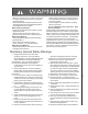
- Misuse of this machine can cause serious injury. - For safety, machine must be set up, used and serviced properly. - Read, understand and follow instructions in the Operating Instructions and Parts Manual which was shipped with your machine. When Setting up Machine: - Always avoid using machine in damp or poorly lighted work areas. - Always be sure the machine support is securely anchored to the floor or the work bench. When Using Machine: - Always wear safety glasses with side shields (See ANSI Z87.
from the work area. Make the workshop completely safe by using padlocks, master switches, or by removing starter keys. 19. Know the tool you are using — its application, limitations, and potential hazards. General Electrical Cautions This saw should be grounded in accordance with the National Electrical Code and local codes and ordinances. This work should be done by a qualified electrician. The saw should be grounded to protect the user from electrical shock.
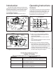
Introduction Operating Instructions This manual includes operating and maintenance instructions for the Wilton 12-inch by 20-inch Cut Off Band Saw, Model 7060. This manual also includes parts listings and illustrations of replaceable parts. Controls Cut-Off Saw Features Refer to Figure 1 and 2 for cut-off saw features Blade Guide Supports Blade Wheel Cover Blade Speed Control Control Panel The operating controls for the saw are provided in a control panel on the left side of the machine.
The bottom row of controls include the following: 1. Stop pushbutton is used to stop the saw blade drive motor. 2. Emergency stop pushbutton is used to quickly disconnect electrical power to the machine. 3. Coolant On/Off selector switch is used to start and stop the coolant pump motor. Other Controls Refer to Figures 1 and 2 for location of the following controls: 1. Drive motor speed control: used to set drive motor speed in meters per minute. 2.
Controlling the Cut: Hydraulic Feed Control The weight of the saw arm provides all the force needed to move the saw blade through the workpiece. In fact, if the full weight of the arm is allowed to make the cut, rapid blade wear and poor cutting accuracy will result. A hydraulic feed control is provided on the control panel to provide the operator with a means to control the speed and efficiency of the cutting operation. The hydraulic cylinder is attached to the saw base and the saw head.
Set Workpiece Against Corner of Right Vise Jaw Angle Setting Block Work Set-up Securing the Workpiece for Square Cuts (see figure 5) 1. Raise the saw head. 2. Slide the left vise jaw far enough to the left to allow the workpiece to be placed in the vise. 3. Place the workpiece on the work table. If the workpiece is long, provide support at the other end. It may also be necessary to provide additional downward clamping to hold the workpiece securely on the work table. 4.
rod. Position the stop post against the work piece and tighten the knob in the stop L-bracket. The stop post can be moved left or right as required to place the stop post against the work piece. Starting the Saw WARNING: NEVER OPERATE THE SAW WITHOUT BLADE COVERS IN PLACE AND SECURED. CAUTION: MAKE SURE THE BLADE IS NOT IN CONTACT WITH THE WORKPIECE WHEN THE MOTOR IS STARTED. DO NOT DROP THE SAW HEAD ON THE WORKPIECE OR FORCE THE SAW BLADE THROUGH THE WORKPIECE. 1. Raise the saw head. 2.
Blade Tracking Hex Adjustment Screws Single Adjustment Screw Center Locking Screws Figure 10: Blade tracking and tensioning screws.) Factory or Field Procedure 1. Raise the saw head enough to allow the saw motor to operate. 2. Loosen four knobs securing the blade cover. Lift the cover and swing it backward. 3. Remove the blade guard mounted on the left blade guide support. 4. Remove both blade guide bearing brackets. NOTE: Maintain proper tension at all times using the blade tensioning mechanism. 5.
Blade Guide Bearing Adjustment Proper adjustment of the blade guide bearings is critical to efficient operation of the cut-off saw. The blade guide bearings are adjusted at the Factory. They should rarely require adjustment. When adjustment is required, adjust immediately. Failure to maintain proper blade adjustment may cause serious blade damage or inaccurate cuts. It is always better to try a new blade when cutting performance is poor.
Test cuts can be used to determine whether or not you have adjusted the blade accurately. Use 2-inch round bar stock to perform these test cuts, as follows: 1. With the bar stock securely clamped in the vise, make a cut through the bar stock. (See figure 14.) 2. Mark the top of the bar stock. 3. Move the bar stock about 1/4-inch past the blade so you can begin a second cut. 4. Rotate the bar stock 180 degrees so the mark you made is now at the bottom of the cut. 5. Make a cut through the bar stock. 6.
Servicing Hydraulic Oil WARNING: SHUT OFF ALL ELECTRICAL POWER TO THE MACHINE 1. Remove hydraulic oil reservoir access panel. 2. Check oil level (refer to Figure 16). If level is below the yellow (upper) line, the reservoir should be filled. 3. Disconnect electrical power. 4. Remove reservoir fill cap. 5. Add oil until the level is at the yellow (upper) line. Install reservoir fill cap. 6.
2. Remove the drive belt from the drive motor pulley (see Changing the Drive Belt). 3. Remove motor pulley. 4. Open the motor junction box and disconnect the power cord wires from their terminals. 5. Remove the nuts, washers and bolts that secure the motor to the mounting plate. 6. Installation of a new motor is a reversal of the above steps. Replacing the Drive Wheel 1. Remove the blade (see Changing Blades). 2. Remove the screw, spring washer, and washer from the speed reducer shaft. 3.
1. Remove front blade guide by removing adjustment knob, spring, and shaft. 2. Remove the rear blade guide by removing its attachment screw 3. Install replacement blade guide in the rear guide location. Secure with attachment screw. 4. Install replacement blade guide in the front guide location. Install shaft into guide. Install spring and adjustment knob. 5. Adjust outermost blade guide using adjustment knob. Set the guide so it just contacts the side of the blade.
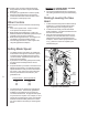
Machine Setup The saw delivered to you has been adjusted at the factory. A number of test pieces have been cut using the saw to verify the accuracy of cutting. Therefore, the only setup operations required before releasing the saw for service are spotting the saw and establishing the electrical connections to the motor. Uncrating and Spotting Spot the saw where it makes the most sense for the operations you will probably be doing.
Wiring Diagram 19
Troubleshooting Fault Probable cause Suggested remedy Excessive blade breakage 1. Material loose in vise. 2. Incorrect speed or feed. 1. Clamp work securely. 2. Check Machinist’s Handbook for speed/feed appropriate for the material being cut. 3. Check Machinist’s Handbook for recommended blade type. 4. Adjust blade tension to the point where the blade just does not slip on the wheel. 5. Start the motor before placing the saw on the workpiece. 3. Teeth too coarse for material. 4.
Troubleshooting (Continued) Blade is twisting 1. Blade is binding in the cut. 2. Blade tension too high. 1. Decrease feed pressure. 2. Decrease tension on blade Unusual wear on side/back of blade 1. Blade guides worn 2. Blade guide bearings not adjusted. 3. Blade guide bearing bracket is loose. 1. Replace blade guides. 2. Adjust blade guide bearings. 1. Blade tooth pitch too coarse for workpiece. 2. Feed too slow; feed too fast. 1. Use blade with finer tooth pitch.
Replacement Parts This section provides exploded view illustrations that show the replacement parts for the Model 7060 12-Inch x 20-Inch Semi-Automatic Horizontal Cut-Off Band Saw. Also provided are parts listings that provide part number and description. The item numbers shown on the illustration relate to the item number in the facing parts listing. Order replacement parts from: WHM TOOL GROUP 2420 Vantage Drive Elgin, Illinois 60124 Ph.
Exploded View – Saw Base - Model 7060 Semi-Automatic Cut-Off Band Saw 11 10 9 8 12 13 1 2 14 15 27 16 17 18 7 21 6 65 66 3 5 20 19 26 29 23 77 48 110 109 117 116 67 68 82 87 88 89 90 91 84 85 86 107 131 121 123 124 106 105 125 104 99 101 100 96 98 95 92 97 94 126 103 102 43 83 70 69 132 128 127 41 71 111 119 120 60 44 73 72 93 58 59 40 61 46 45 81 108 118 129 54 62 80 76 114 115 122 53 63 64 47 113 112 130 38 34 24 75 74 133 37 22 25
Parts List – Saw Base - Model 7060 Semi-Automatic Cut-Off Band Saw Ref No.
Parts List – Saw Base - Model 7060 Semi-Automatic Cut-Off Band Saw, (Continued) Ref No.
Exploded View – Saw Head - Model 7060 Semi-Automatic Cut-Off Band Saw 146 147 148 149 167 171 150 166 163 164 168 158 165 152 162 161 156 159 169 153 154 155 201 230 157 200 199 173 205 203 228 198 206 204 227 174 197 196 207 195 175 226 231 225 209 208 222 224 232 220 218 236 235 244 190 211 185 184 183 182 181 193 213 See Detail 'A' 248 259 246 249 258 251 252 257 256 255 247 253 254 178 192 214 239 240 241 243 212 177 191 215 238 245 194
Parts List – Saw Head - Model 7060 Semi-Automatic Cut-Off Band Saw Ref No.
WHM TOOL GROUP 2420 Vantage Drive Elgin, Illinois 60124 Ph.