
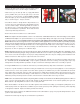
Owner manual


1
2
3
3A
4
5
5A
6
7
1
2
2
2
1
2
2
4
4
249-12231/32
300-11337
160-9986
160-9814/15-BK
150-8936K
120-11875-BK
120-11875-RD
300-5968
230-10933
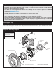
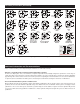
Bracket Kit (pair, one each, left and right)
Adapter, Rotor Registration
Rotor, ULHP - .81” x 12.19” Dia.
Rotor, Black, SRP Drilled and Slotted (one each, right and left)
Pad, BP-10 Compound, Axle Set
Caliper, D154, Black
Caliper, D154, Red
Sleeve
Slide Pin Bolt
ITEM NO. PART NO. DESCRIPTION QTY
NOTES: Item 3A is an optional item and is included in the “-D” kits. Add “-D” to end of part number when ordering.
Item 5A is an optional item and is included in the “-R” kits. Add “-R” to end of part number when ordering.
Parts List
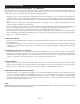
General Information
•Installation of this kit should ONLY be performed by persons experienced in
the installation and proper operation of disc brake systems. Before
assembling this Wilwood rear disc brake kit, double check the following to
ensure a trouble free installation.
•Inspect the contents of this kit against the parts list to ensure that all
components and hardware are included.
•Make sure this is the correct kit to fit the axle housing flange, not necessarily
the rear end make. Many times aftermarket manufacturers put a different
make of axle housing flange on the stock rear end housing (Figure 5).
Example; Big Ford rear ends with Olds-Pontiac flanges, therefore, an Olds-
Pontiac rear disc brake kit would be the correct kit to order. Also, shock
clearance may be a problem. They may have to be modified and/or relocated
to clear the Wilwood kit after final assembly.
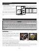
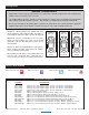
•Verify your wheel clearance using Figure 2.
•Verify The Following Measurements Before Assembly.
• Bearing outside diameter.
• Axle housing flange mounting pattern to pattern in bracket.
• Stud pattern on axle flange to stud pattern in hat.
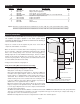
• Axle center register diameter is 2.80”, Figure 3. This kit uses Wilwood’s
removable center register adapters. Rotors can either be centered on
the axle register, i.e. register-centric or centered on the wheel studs, i.e.
stud-centric. Due to variations in wheel stud final diameters, register-
centric centering can be a more accurate method of centering the rotor
to the axle. Wilwood offers various diameter adapters for purchase in
addition to the ones supplied in this kit, see Table 1.
• Dimension from wheel side of axle flange to wheel side of axle housing
flange (see Figure 5, lower right hand corner). This dimension is critical
to ensure proper alignment of the rotor to the caliper, and should match
offset given in the kit description.
• The Wilwood hat utilized in this kit is drilled for 1/2” diameter wheel studs. NOTE: Some OEM axles have 7/16” (0.44”) wheel axle
studs. It is recommended that you upgrade to 1/2” studs. Dependent on the type of axle, this may be a simple stud change, or
may require the services of a machine shop to perform.
• Maximum axle flange diameter must be no larger than 6.61” w/.050” x 45° chamfer, Figure 3.
Figure 2. Wheel Clearance Diagram
1.69 (42,9)
CENTER
LINE OF
WHEEL
1.00 (25,4)
RADIUS
20°
..81 (20,6)
4.04
(96,5)
7.50
(190,5)
WILWOOD ROTOR
WHEEL MOUNT
SURFACE
NOTE: A MINIMUM OF .080” CLEARANCE MUST BE MAINTAINED
BETWEEN THE WHEEL AND CALIPER IN ALL AREAS
.81 (20,6) ROTOR THICKNESS
2.80 (71,1)
CENTER REGISTRATION
CALIPER
Page 3