
Owner manual


Disassembly Instructions:
•Disassemble the original equipment rear brakes:
Raise the rear wheels off the ground and
support the rear suspension according to the
vehicle manufacturer’s instructions.
Remove the rear wheels and disassemble the
drum brake assembly down to the bare axle.
•Remove any nicks or burrs on the axle housing
flange, as well as the axle flange, that may interfere
with the installation of the new brake components.
•Clean and de-grease the axle and axle housing
flange.
Assembly Instructions
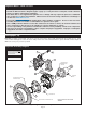
(numbers in parenthesis refer to the parts list, and Figure 1 on the preceding pages): CAUTION: All mounting
bolts must fully engage threaded holes.
•Orient the bracket assembly (1) as shown in Figure 1, and mount
to the axle housing flange using the Original Equipment
Manufacturer (OEM) bolts and nuts, Figure 1. Ensure that the
bracket assembly backing plate fits flush against the axle
housing flange. Apply red Loctite® 271 to the OEM bolt threads
and torque to OEM specifications.
•Install the axle into the rear end housing.
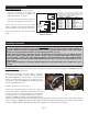
•Slide the rotor registration adapter (2) onto the axle register on
the axle flange with the smaller O.D. facing toward the rotor/hat
(3), Photo 1. Align the correct hole pattern in the rotor/hat with
the stud pattern on the axle flange and slide into place, Figure 1
and Photo 2. NOTE: The rotor/hat must fit flush against the axle
flange or excessive rotor run out may result. Install three lug nuts (finger tight) to keep the rotor/hat assembly in place while continuing
with the installation. NOTE: Some OEM and after market axles come with stud sizes larger than 0.50” diameter. Verify stud size
and have a qualified machine shop drill the bolt circle of the hat/rotor to the correct stud size, if necessary.
Page 4
Assembly Instructions
IMPORTANT:
• To ensure maximum performance from your parking brake system, the cables must be routed as straight as
possible. Bends in the cable can significantly reduce efficiency and thus reduce pull force at the brake. Tight
bends must be avoided with a minimum recommended bend radius of 6" to 8".
• Cables should be properly restrained to prevent "straightening" of bends when tension is applied. Restrain
movement of cable by affixing the cable sheath to body or chassis by fitting cable clamps at various points
over the length of cable or by using original equipment cable attachments points. The clamping method
chosen will require that cable sheath be held tightly without movement, crushing or causing interference to the
internal cable.
• Cables must be initially pre-stretched by multiple applications of the brake handle, then re-adjusted to correct
tension.
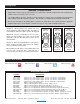
Disassembly Instructions
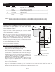
Figure 3. Axle Flange
Maximum Dimension
MAXIMUM
DIA 6.61"
TO FIT
WILWOOD
HAT
2.80”
REGISTER
.050 X 45°
CHAMFER
Table 1. Center Register Adapters
This kit includes a 3.06” center I.D. hat or rotor assembly and a 2.80” hub
register adapter ring to accommodate the installation of this kit on axles of
either dimension. For axles with different center register diameters, please
consult the table below for optional adapter ring sizes.
PART NO. REGISTER I.D. NOTE
NO ADAPTER USED
300-11732
300-11962
300-11338
300-11337
300-11532
300-11803
300-11901
300-11653
300-11339
3.06”
2.86”
2.84”
2.82”
2.80”
2.78”
2.52”
2.50”
2.18”
2.00”
ROTOR CENTER HOLE I.D.
OPTIONAL
OPTIONAL
OPTIONAL
SUPPLIED WITH KIT
OPTIONAL
OPTIONAL
OPTIONAL
OPTIONAL
OPTIONAL (Machine to fit I.D.)
Photo 2Photo 1
Small
O.D.
toward
rotor/hat