
Owner manual


Page 5
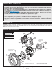
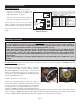
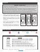
•Install the disc brake pads (4) into the caliper (5) with the friction
material facing the rotor, as shown in Figure 1 and Photo 3.
•Install sleeves (6) onto slide pin bolts (7). Apply white lithium
grease (available from your local auto parts store) to the slide
pins/sleeves, as shown in Photo 4. Do not apply to threads.
Mount the
caliper (5) onto the mounting bracket (1) using slide pin
bolts, as shown in Figure 1. Torque to 35 ft-lbs.
•Check wheel clearance: Gently slide the caliper inboard, so as
to remove any excess gap between the outboard brake pad, the
rotor face and the caliper. This will approximate the location of
the caliper in service. Temporarily install the wheel and torque
lug nuts to manufacturer’s specification. Ensure that the wheel
rotates freely without any interference.
•Remove wheel and connect brake hose as outlined below.
•NOTE: The caliper in this brake kit utilizes a 10mm x 1.50 thread inlet. OEM rubber brake hoses with 10mm fittings can be adapted
to Wilwood D154 calipers. The preferred method is to use steel banjo adapter fittings at the caliper, and enough steel braided line to
allow for full suspension travel. Carefully route hoses to prevent contact with moving suspension, brake or wheel components.
NOTE: Wilwood hose kits are designed for use in many different vehicle applications and it is the installer's responsibility to properly
route and ensure adequate clearance and retention for brake hose components. Wilwood offers universal brake flex line hose kits,
for 3/8-24 IF chassis fittings order P/N 220-12104 for the 14 inch length, P/N 220-12105 for the 18 inch length, or P/N 220-12106 for
the 22 inch length. For 10mm x 1 BF chassis fittings order P/N 220-12107 for 18 inch length. Hose kits include hoses, fittings,
banjo bolts, etc. all in one package for use with this caliper.
•NOTE: Specified brake hose kits may not work with all Years, Makes and Models of vehicle that this caliper kit is applicable to due to
possible OEM manufacturing changes during a production vehicle's life. It is the installer's responsibility to ensure that all fittings and
hoses are the correct size and length to ensure proper sealing and that they will not be subject to crimping, strain and abrasion from
vibration or interference with suspension components, brake rotor or wheel.
•If using a Wilwood flexline hose kit, proceed as follows: Do not lubricate bolt. With two new crush washers installed, torque bolt to
96 - 120 in-lbs. (do not exceed 144 in-lbs). Torque to lighter specification and check for leakage, increasing torque only to stop
leakage without exceeding maximum specification. Replace crush washers and banjo bolt whenever re-assembly is required.
•If reusing the OEM brake hoses, install new crush washers (not included) and torque banjo bolt to manufacturer’s specification.
•In absence of specific instructions for brake line routing, the installer must use his best professional judgment on correct routing and
retention of lines to ensure safe operation. Test vehicle brake system per the 'minimum test' procedure stated within this document
before driving. After road testing, inspect for leaks and interference. Initially after install and testing, perform frequent checks of the
vehicle brake system and lines before driving to confirm that there is no undue wear or interference not apparent from the initial test.
Afterwards, perform periodic inspections for function, leaks and wear in a interval relative to the usage of vehicle.
•NOTE: Clevis and cable kits which attach to the parking brake assembly are not included in the Wilwood parking brake kit. Wilwood
offers a generic style parking brake cable kit, P/N 330-9371 for this application which can be ordered separately from your local
Wilwood dealer or by calling Wilwood customer service at (805) 388-1188.
•Before final installation of the wheel, remove the rubber grommet in the bracket kit assembly (1) and adjust the parking brake shoes
outward (using a drum shoe adjustment tool available at your local auto parts store) while spinning the rotor/hat (3) until a slight drag
is felt against the hat/drum. Replace the rubber grommet when finished.
•Bleed the brake system, referring to the additional information and recommendations on page 7 for proper bleeding instructions. Check
system for leaks after bleeding.
•Install the wheel and torque the lugs nuts to manufacturer’s specifications.
Assembly Instructions (Continued)
Photo 3 Photo 4