P4-EPC / B-E1, B-E2 With Socket-Based Intel Celeron, Intel Pentium IV, Mobile Intel Pentium IV Processor - M Operating Manual
P4-EPC / B-E1, B-E2 Operating Manual Edition Feb 2006
NO PART OF THIS MANUAL, INCLUDING THE PRODUCTS AND SOFTWARE DESCRIBED IN IT, MAY BE REPRODUCED, TRANSMITTED, TRANSCRIBED, STORED IN A RETRIEVAL SYSTEM, OR TRANSLATED INTO ANY LANGUAGE IN ANY FORM OR BY ANY MEANS, EXCEPT DOCUMENTATION KEPT BY THE PURCHASER FOR BACKUP PURPOSES, WITHOUT THE EXPRESS WRITTEN PERMISSION OF MANUFACTURER.
Contents Contents MANUFACTURER’S CERTIFICATION ..................................................1 T ESTED SAFETY ...........................................................................................1 FCC-CLASS A DECLARATION........................................................................1 NOTE ON THE LASER .....................................................................................1 IMPORTANT NOTES.......................................................................................
Contents USB PORTS 3 & 4 (T WO 4-PIN UNIVERSAL SERIAL BUS) ...............................20 MIDI/GAME CONNECTOR (GOLD 15-PIN GAME_AUDIO)..............................21 AUDIO PORT CONNECTORS (T HREE 1/8” GAME_AUDIO)............................21 SERIAL PORT COM1 CONNECTOR (T EAL/T URQUOISE 9-PIN MALE).................22 SERIAL PORT COM2 CONNECTOR (9-PIN MALE) ...........................................22 PARALLEL PORT CONNECTOR (BURGUNDY 25-PIN PRINTER) .......................23 APPENDIX ................
Manufacturer’s Certification Manufacturer’s Certification The device complies with the requirements of the EEC directive 89/336/EEC with regard to “Electromagnetic compatibility” and 73/23/ECC “Low Voltage Directive”. Therefore, you will find the CE mark on the device or packaging. Tested Safety In addition, the P4-EPC has received the UL symbol and cUL symbol.
Important notes Important notes The P4-EPC system is a computer for manufacturer’s usage. It is conforming to the current safety standards for data processing equipment. If this device is taken from a cold environment into the operating room, moisture condensation may form.
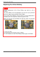
Replacing the Lithium battery Replacing the Lithium Battery CAUTION: Incorrect replacement of the Lithium Battery may lead to a risk of explosion The lithium battery must be replaced by the end user only by identical batteries or types recommended by Wincor Nixdorf. Do not throw Lithium Batteries into the trashcan. It must be disposed of in accordance with local regulations concerning special waste Make sure that you insert the Battery the right way round.
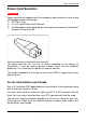
Power cord selection Power Cord Selection IMPORTANT: Power cord are not supplied with the equipment and consumers have to use certified power cord, for example, 1) CCC for China 2) UL, cUL and CSA for North America 3) Certified power cord approved by home governing body for Continental Europe, UK and Australia The power cord for this unit has to select according to the country of destination. It must be used to prevent electric shock.
Power cord selection Table A: Cord Type Size of Conductors in Cord Maximum Current Rating of Unit SJT 18 AWG 16 AWG 10 Amps 12 Amps 14 AWG 12 Amps 18 AWG 10 Amps 17 AWG 12 Amps SVT For units set at 115 V: Use a parallel blade, grounding type attachment plug rated 15 A, 125 V. For units set at 230 V (domestic use): Use a tandem blade, grounding type attachment plug rated 15 A, 250 V.
Power cord selection For units set at 230 V (outside of the United States and Canada): Use a cord set consisting of a minimum AWG according to Table A and a grounding type attachment plug rated 15 A, 250 V. The cord set should have the appropriate safety approvals for the country in which the equipment will be installed and should be marked HAR.
Features – P4-EPC /B-E1 FEATURES – P4-EPC /B-E1 Main Features PROCESSORS Intel Pentium IV, Intel Celeron, PGA478 CHIP SET Intel 845G, Brookdale-G FSB 400/533 MHz (100/133 MHz Bus Clock) 4X AGP BIOS 2M Flash EPROM Plug-and-Play Specification 1.
Features – P4-EPC /B-E1 8 POWER INPUT Nominal voltage: 100-120V / 200-240V Frequency: 50 ~ 60 Hz Current: 6/3A DIMENSIONS 136 (H) x 427 (W) x 404 (D) in mm P4-EPC /B-E1, B-E2 – Operating Manual 1750100230 C
Features – P4-EPC /B-E1 Processor Supported INTEL PROCESSOR PROCESSOR SPEED FRONT SIDE BUS INTEL PENTIUM IV 2.0GHZ 400MHZ 2.8GHZ 533MHZ 1.7GHZ 400MHZ 2.
Features – P4-EPC /B-E2 FEATURES – P4-EPC /B-E2 Main Features PROCESSORS Mobile Intel Pentium IV Processor-M, Intel Pentium IV, Intel Celeron, PGA478 CHIP SET Intel 845GV FSB 400/533 MHz (100/133 MHz Bus Clock) BIOS 2M Flash EPROM Plug-and-Play Specification 1.
Features – P4-EPC /B-E2 FLOPPY DISKETTE DRIVE 1.
Features – P4-EPC /B-E2 Processor Supported INTEL PROCESSOR M OBILE INTEL PENTIUM IV PROCESSOR-M INTEL PENTIUM IV INTEL CELERON PROCESSOR SPEED FRONT SIDE BUS 1.7GHZ 400MHZ 2.2GHZ 400MHZ 2.0GHZ 400MHZ 2.8GHZ 533MHZ 1.7GHZ 400MHZ 2.
Functions & Indicators on the P4-EPC FUNCTIONS & INDICATORS ON THE P4-EPC 6 5 2 4 3 1 7 1 – ON/OFF Button In an ATX based system, the new soft touch power button replaces the main power switch that turns your system on and off. From an OFF state, you can switch the system ON by simply pressing the power button. From an ON state, pressing and holding the power button for four (4) seconds can turn OFF the system.
Functions & Indicators on the P4-EPC 7 – USB Connector (Front Panel) Two contact points are meant for connection of Universal Serial Bus (USB) Devices.
Drives on the P4-EPC DRIVES ON THE P4-EPC 5¼" CD-ROM DRIVE 3½" HDD 3½" FDD The P4-EPC has two drive slots for externally accessible drives. Two further 3.5" drive slots are available for the installation of hard disks. The following drives may be used in the P4-EPC: 3½" drive slot for Floppy Drive 3½" Hard-Disk Drive 5¼" drive slot for CD-ROM or DVD-ROM Drive Floppy Drive The 3½" Floppy Drive supports capacities of up to 1.44 MB.
Back Panel Connectors on the P4-EPC PCI-SLOT #5 PCI-SLOT #4 PCI-SLOT #3 PCI-SLOT #2 PCI-SLOT #1 2x USB Slot +12V Supply at 2A (max) Game and Audio Port BACK PANEL CONNECTORS ON THE P4-EPC COM 6* POWER-SUPPLY UNIT COM 5* COM 2 Mouse Keyboard 16 Parallel Port COM1 LAN RJ45 CRT 2 x USB P4-EPC /B-E1, B-E2 – Operating Manual DVI Connector 1750100230 C
Back Panel Connectors on the P4-EPC Power-Supply Unit Power Supply Specification AC Out AC INPUT LIVE-VOLTAGE WIPER-SWITCH TYPE NOMINAL VOLTAGE Standard SFX switching CURRENT 6/3A FREQUENCY AC IN SELECTION 50 / 60 Hz Wiper-Switch AC O UT Yes POWER ON-OFF SWITCH No APPROVAL EN61000 100-120V / 200-240V W ARNINGS: Before connecting the P4-EPC system unit to the line voltage, if the rated voltage does not agree with the local line voltage, you must move the wiper switch to the correct position
Back Panel Connectors on the P4-EPC On-board DVI (TFT Flat Panel Display) DVI-D Connector The motherboard has an on-board DVI-D connector supporting standard DVI digital flat panel display. The on-board Silicon Image SiI164 transmitter encode the digital output from the Intel DVO interface of the 845GV to TMDS output for the DVI interface. It is capable of driving a digital display up to 1024x768 at 60Hz.
Back Panel Connectors on the P4-EPC PS/2 Mouse Connector (Green 6-pin Mini-DIN) PS/2 Mouse (6-pin Female) This connector is for a standard Mouse using a PS/2 plug (mini DIN). PS/2 Keyboard Connector (Purple 6-pin Mini-DIN) PS/2 Keyboard (6-pin Female) This connector is for a standard Keyboard using a PS/2 plug (mini DIN).
Back Panel Connectors on the P4-EPC USB Ports 1 & 2 (Two 4-pin Universal Serial Bus) USB1 Universal Serial Bus (USB) 2 Two USB ports are available for connecting USB devices. USB Ports 3 & 4 (Two 4-pin Universal Serial Bus) USB3 USB4 Two USB ports are available for connecting USB devices.
Back Panel Connectors on the P4-EPC MIDI/Game Connector (Gold 15-pin GAME_AUDIO) Joystick/MIDI (15-pin female) You may connect game joysticks or game-pads to this connector for playing games. Connect MIDI devices for playing or editing professional audio. Audio Port Connectors (Three 1/8” GAME_AUDIO) Line Out Line In MIC Line Out (lime) can be connected to headphones or preferably powered speakers.
Back Panel Connectors on the P4-EPC Serial Port COM1 Connector (Teal/Turquoise 9-pin Male) COM1 Serial Port (9-pin male) Standard Serial port COM1 is ready for a mouse or other serial devices. Serial Port COM2 Connector (9-pin Male) COM 2 Serial Port (9-pin male) Standard Serial port COM2 is ready for a mouse or other serial devices. This second serial port is available using a 9-pin DSUB-Male cable assembly connected from the motherboard COM2 dual-row headers to a back panel.
Back Panel Connectors on the P4-EPC Parallel Port Connector (Burgundy 25-pin PRINTER) Parallel (Printer) Port (25-pin female) The connector for the parallel ports which supporting standard SPP and as wells as bi-directional EPP/ECP.
Appendix Appendix Technical data for the P4-EPC Footprint Width Depth 427 mm 404 mm Total height 136 mm Weight approx. 11 kg Climatic category IEC 721-3-3 Class 3K3 Transport Storage Operating temperature Input voltage IEC 721-3-2 Class 2K2 -2.
Appendix Model Type and Series for P4-EPC Model Type / Series Description P4-EPC /B-E1 Used metal enclosure except top and bottom, with vent openings on left and rear side. With additional vent openings on front bezel. System using P195 motherboard. P4-EPC /B-E2 Used metal enclosure except top and bottom, with vent openings on left and rear side. With additional vent openings on front bezel. System using P195+ motherboard.
Published by Wincor Nixdorf Pte Ltd 2, Kallang Sector Singapore 349277 Part No.