
- Spencer Installing and Operating Instructions Vacuum Cleaning Systems A,B,C, D ,V

4
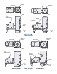
Stationary Model. No special foundation is required. A level
concrete floor or pad is recommended, although any other
substantial floor is satisfactory. The Industravac base should
be placed on rubber isomode pads furnished with the unit.
In selecting an installation site for a stationary Industravac
model, be sure the unit is readily accessible for servicing by
allowing several feet of clearance around the machine. The
exhaust should discharge outdoors or into a room having
ample volume and sufficient ventilation to allow air to escape.
Avoid placing the Industravac unit in an enclosed room where
a substantial heat buildup might occur. The ambient temper-
ature should not exceed 104°F (40°C).
Unpacking
1. Uncrate the Industravac unit, saving all literature, boxes
and parts.
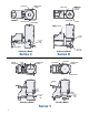
NOTE: The D Series Industravac is shipped on two skids:
the frame with vacuum producer on one skid, and the
separator horizontally mounted on the other skid. To
assemble the two units, attach the rubber inlet sleeve to
the vacuum producer inlet; lift the separator at the lifting
points, position it on the frame and align the rubber
sleeve and bolt holes. Secure with bolts provided.
2. Remove packing materials, plugs, etc.
3. Use the packing slip to check off and confirm the pres-
ence of all ordered components.
4. Lower the dirt can by raising the bail arm in front of the
separator and look inside for parts and optional accessories
(e.g., equalizing line, dirt can bags, motor starter, hose,
tools) which are often shipped loose in this location.
5. Read all instructional and warning labels on the machine
before operation.
Industravac Setup
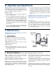
1. Vacuum producer. The upblast exhaust tubing on A, B
and D Series units will accept, if required, an air gate (throt-
tling valve), discharge silencer, tubing connection and
weather cap. The C Series has a bottom exhaust with
silencer, Patent No. 4,874,410, as standard equipment.
(Optional adapter P/N PLT90023 can be purchased to pro-
vide a 6" O.D. tube connection.) The V Series equipped with
exhaust diffuser for
weather protection
and a relief valve for
load control. If any
optional items have
been purchased for
field installation, they
should be mounted
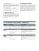
on the exhaust tubing with the air gate first, followed by a
flexible connector (see diagram and caution below), silencer
and weather cap or tubing.
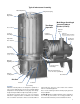
CAUTION: Tubing connected to the vacuum producer
should be properly aligned and supported so there is no
stress on the machine casing. The tubing must not
touch the vacuum producer. Use a flexible connector to
create an isolating gap of approximately 1" minimum
and clamp it in place for an air-tight seal.
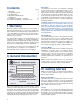
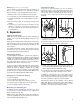
2. Separator. Open the separator access door to confirm
that the door gasket and filter bags are in place and secure.
With the door open, operate the external bag shaker to
check for proper action.
Lower the dirt can to see that nothing has been left inside
inadvertently, and check that the dirt can gasket is in place
beneath the separator. Raise the dirt can, making sure it
seals tightly against the gasket. Inspect both separator inlet
ports to be sure they are clear.
If optional dirt can liners will be used, install one liner in the
dirt can and make sure the equalizing line is in place, properly
connected to the separator and dirt can.
CAUTION: The dirt can liner must not be used without
the equalizing line (the liner will be sucked out of the
can, up against the filter bags) and vice versa (without
the liner in place, mechanical and environmental damage
may result)
CAUTION: If the separator is equipped with an optional
explosion relief port, it must be installed in accordance
with the National Fire Code and all applicable safety
regulations. The port should be positioned away from
nearby personnel and ducted to the outdoors.
3. Electrical.
NOTE: All wiring and electrical adjustments or installations
should be done by a qualified electrician in accordance with
the National Electrical Code and local codes.
The standard electrical motor furnished with the A, B and D
Series Industravac vacuum producer is a NEMA design B,
open drip proof induction type motor suitable for 60 Hz, 3-
phase, 200-230/460VAC operation. The C Series and V
Series have a TEFC type motor as standard. Other motors
such as TEFC and explosion-proof types, and other volt-
ages, may be furnished as required by the application.
CAUTION: The electrical service at the installation site
must supply the voltage stamped on the motor name-
plate. Operation at an incorrect voltage will result in a
damaged motor.
Industravac portable units are furnished with a starter and
50-ft cable, requiring only a suitable male plug for connec-
tion. In making the electrical connections for a stationary
Industravac, follow the wiring instructions furnished. All
wiring, power cords and circuit breakers should be of ample
capacity to ensure that proper voltage is maintained at the
motor terminals while starting and running. Starters should
have thermal overload protection and low-voltage protection.
Electrical Accessories. Certain optional accessories such as
an Electronic Modulating Bleed Control and motorized filter
bag shaker require 115VAC, single-phase electrical service.
Such accessories should be installed using the separate
instruction sheets accompanying them.
A grounding lug is provided for those Industravac units having
optional grounded filter bags. In order to effectively bleed off
static electricity charges, this lug should be securely connected
to an electrical ground.
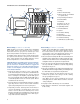
4. Motor Rotation. Perform a pre-start check to make sure
the motor turns in the correct direction. (While the vacuum
producer will operate both ways, its performance will be
greatly diminished if it runs backward.) If V Series rotation is
incorrect, it will perform as a blower, not a vacuum producer.
A rotation direction arrow is located on the vacuum producer
casing. To see if the motor is wired correctly, momentarily
start the motor. "Bump" or jog the start button and observe
the direction of rotation at either the end bell of the motor or
the motor shaft, whichever is visible. If the rotation is incor-
rect, the motor wiring must be reversed.
Tubing by
Customer
Clamps
Rubber
Sleeve