
- Spencer Installing and Operating Instructions Vacuum Cleaning Systems A,B,C, D ,V

7
V. Maintenance
CAUTION: Disconnect electrical power before performing
any maintenance procedure.
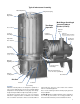
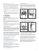
1. Lubrication
1. Motor. Follow motor manufacturer's recommendations.
For following items 2 through 4, apply light lubricating oil
yearly or more often as needed.
2. Bag shaker rod. Grease yearly or more often as needed.
3. Lift cams, left- and right-hand.
4. Dirt can casters.
5. Wheels of portable model. Grease yearly or more often
as needed. (No lubrication is required for the fifth wheel
of large portable models.)
2. Vacuum Producer
NOTE: For maintenance of the Vortex regenerative vacuum
producer, equipped on Series V models, see handling,
installing and operating instructions Form ZZ.
NOTE: For maintenance of the motor, consult motor manu-
facturer's information provided with the equipment.
NOTE: Disassembly, repair or alteration cannot be done by
unauthorized personnel during the warranty period without
voiding the warranty. The maintenance instructions that follow
are provided as a customer service to facilitate field repair
after the warranty period.
NOTE: An Industravac vacuum cleaning system consists of
the Industravac unit and its associated components. The
vacuum producer is designed for operation under load,
hence it must always be connected directly to hose and
tools or to a tubing system with hose and tools.
Machine startup
1. Turn the Industravac unit on, having fully completed the
previous setup procedures.
2. (For units equipped with discharge air gate.) With a full
vacuum system load connected to the separator inlet(s),
connect an ammeter to the motor circuit. Measure the
draw (amperage) of the motor. If it is below the full load
current rating, open the air gate until the amperage reach-
es, but does not exceed, the full-rated motor capacity.
The air gate should then be fixed to prevent opening
beyond this point.
3. (For units equipped with Electronic Modulating Bleed
Control.) Follow adjustment instructions in the separate
data sheet accompanying the EMBC.
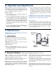
4. Check the tubing system and vacuum equipment for
leaks. At the separator, check the access door, dirt can
seal and hose inlet valves. Examine all hoses, tubes,
and fittings connected to the Industravac unit. Air leaks
are highly detrimental to the overall system perfor-
mance, wasting power and impairing the operating
efficiency.
CAUTION: When the vacuum producer is operating, its
housing will be hot to the touch. Use caution when
making inspections or adjustments in this area.
Hose and tools
For optimum performance, Industravac units should be used
only with complementary Spencer vacuum cleaning equip-
ment system components—Spencer tubing, fittings, flexible
hose, tools, attachments and accessories. These products
have been designed and sized specifically for compatible
use in an Industravac system.
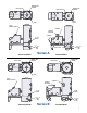
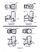
2. Bag Shaker
Rod
1. Motor
3. Lift
Cams
4. Dirt Can
Casters
5. Wheels of
Portable Model
IV. Operation and Adjustments
If operating problems are detected, notify your local Spencer
Representative, describing the situation in detail before
attempting repairs or disassembly.
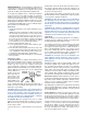
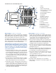
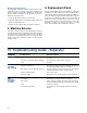
The Industravac vacuum producer has an overhung type
construction with multiple impellers mounted directly on the
motor shaft. The motor bearings support the shaft and
impeller assembly.
Six impellers and five deflectors are shown in the accom-
panying diagram of a typical vacuum producer; the actual
number of each will vary from two to nine, depending on
the model.
– Multi-stage Centrifugal (Series A, B, C & D)