
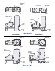
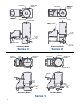
- Spencer Installing and Operating Instructions Vacuum Cleaning Systems A,B,C, D ,V

Reassembly (For Series V see Form ZZ)
1. Bolt the motor down tightly in its original position with the
shaft in the exact center of the vacuum producer casing.
Be sure that shims (if removed) are replaced in their
exact positions on the same attach-points as before. See
that packing #3 is in place and tight around the shaft.
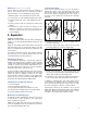
2. Place the last-removed impeller #9 on the shaft and push it
toward the motor until it bottoms. Position the impeller same
distance from the division head as noted during disassembly
and tighten. Rotate once by hand to check placement.
3. Place the last-removed deflector #8 back tightly against
the stops and, with a suitable tool, caulk the rope packing
#5 firmly into the groove.
4. Place the next impeller on the shaft. Push it toward the motor
until it bottoms. Back it off approximately 1/8" and tighten it to
the shaft. Rotate once by hand to check placement.
5. Place spacer #12 into the last deflector. Place the next
deflector into position in the casing as shown, caulking
the rope packing into the groove.
Note: Make sure the spacer and deflector are pressed
back tightly and at a uniform distance from the end of the
casing at all points.
6. Repeat procedure until all stages are reassembled.
7. Align gasket #11 and division end head #7 together and
bolt to casing.
8
Disassembly (For Series V see Form ZZ)
NOTE: Read these procedures carefully before attempting
disassembly. Refer to the diagram on page 7 and the
instructions below as you proceed. Contact your local
Spencer Representative for help if any questions arise.
To facilitate repairs, disconnect the vacuum producer from
the separator and unbolt the casing from the Industravac
frame. Using adequate and safe lifting equipment, remove
the vacuum producer to a convenient work location.
CAUTION: During reassembly, parts must be installed in
exactly the same relative positions. Therefore, as each
part is removed, it should be marked or tagged and
stacked in sequence. It is especially important that the
location of each impeller, as well as its rotated position
on the shaft, be marked.
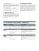
1. Begin at the intake and remove, in turn, end head #7,
(some models may have an extra spacer and half deflector
inserted during manufacturing; these must be removed
before reaching the first impeller), impeller #9A, spacer
#12, rope packing #5, deflector #8A, impeller #9B, and so
on until all impellers have been removed. (Note: division
head #4 cannot be removed.)
2. Check the division head packing #3 and replace it if dam-
aged. Any time the motor is removed and reinstalled,
replace this packing before the motor is put in place.
3. Temporarily reconnect electrical power and run motor to
check for mechanical or electrical defects. If the motor
must be removed, disconnect electrical power, remove
bolts #15 and slide motor straight back, being careful not
to damage packing #3 around shaft or the shims (if pre-
sent) under each motor attach-point.
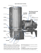
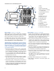
1 Motor
2 Casing
3 Division Head Packing
4 Division Head (not available
as separate item)
5 Rope Packing for Deflector
6 End Head Bolts
7 End Head
8 Deflectors (A, B, etc.)
9 Impellers (A, B, etc.)
10 Split Clamped Hub
11 End Head Gasket
12 Spacers
13 Front Motor Bearing
14 Motor Base
15 Motor Hold-Down Bolts
16 Rear Motor Bearing
17 Half Deflector (not all models)
17
10
12
13
14
15
16
2
1
3
4
5
6
7
8
Exhaust
Outlet
Inlet
11
Circled items are recommended spare parts
9