
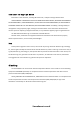
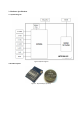
Specifications

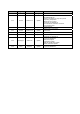
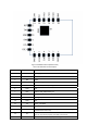


16 IO12 GPIO12;HSPI_MISO
17 IO14 GPIO14;HSPI_CLK
18 GND GND
19 GND GNDPAD
Note:
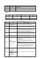
Table‐2PinMode
Mode IO15 IO0 IO2
UARTDownload
Mode
Low Low High
FlashBootMode Low High High
Table‐3InterfaceDescription
Name Pin FunctionDescription
HSPI
Interface
IO12(MISO),IO13(MOSI),I
O14(CLK),IO15(CS)
CanconnectexternalSPIFlash,displayandMCUetc.
PWM
Interface
IO12(R),IO15(G),IO13(B)
Theofficialdemoprovides4‐channelPWM(usercanexpand
to8‐channel),canbeusedtocontrollights,buzzers,relays
andmotors,etc.
IRInterface IO14(IR_T),IO5(IR_R)
ThefunctionalityofInfraredremotecontrolinterfacecanbe
implementedviasoftwareprogramming.NECcoding,
modulation,anddemodulationareusedbythisinterface.The
frequencyofmodulatedcarriersignalis38KHz.
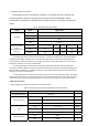
ADC
Interface
ADC
ESP8266EXintegratesa10‐bitprecisionSARADC.
ADC_INinterfaceisusedtotestthepowersupplyvoltageof
VDD3P3(Pin3andPin4),aswellastheinputvoltageofTOUT
(Pin6).Itcanbeusedinsensorsapplication.
I2CInterface IO14(SCL),IO2(SDA) Canconnecttoexternalsensoranddisplay,etc.
UART
Interface
UART0:
TX0(U0TXD),RX0(U0RXD),
IO15(RTS),IO13(CTS)
UART1:IO2(TX0)
DeviceswithUARTinterfacescanbeconnected
Download:U0TXD+U0RXDorGPIO2+U0RXD
Communication:
(UART0):U0TXD,U0RXD,MTDO(U0RTS),MTCK(U0CTS)
Debug:UART1_TXD(GPIO2)Canbeusedtoprintdebugging
information
Bydefault,UART0willoutputsomeprintedinformationwhen
thedeviceispoweredonandisbootingup.Ifthisissueexerts
influenceonsomespecificapplications,userscanexchange
theinnerpinsofUARTwheninitializing,thatistosay,
exchangeU0TXD,U0RXDwithU0RTS,U0CTS.
I2SInterface
I2Sinput:
IO12(I2SI_DATA);
IO13(I2SI_BCK);
IO14(I2SI_WS);
Mainlyusedforaudiocapturing,processingandtransmission.
I2Soutput:
IO15(I2SO_BCK);
IO3(I2SO_DATA);
IO2(I2SO_WS);