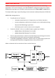
MPR30-IEM User Manual High performance True diversity Receiver SN: ________________ Rev. 02 (rif. FW v1.
BRIEF DESCRIPTION MPR30 is a compact true diversity receiver designed for professional in-ear monitoring applications. This receiver features a real TRUE DIVERSITY configuration along with a unique wideband tuning range up to 232 MHz. Audio processing can be Stereo MPX or mono based. The output audio stage is especially design to have maximum audio peak-dynamic of 200 mW. MPR30-IEM is designed to be: “easy & quick to use” thanks to o automatic setup functions (i.e.
SAFETY INSTRUCTION Read this safety instruction and the manual first Follow all instructions and information. Do not lose this manual. Do not use this apparatus under the rain or near the water. Do not install the apparatus near heaters or in hot environments, do not use outside the operating temperature range. Do not open the apparatus, only qualified service technician are enabled to operate on it.
BATTERIES MPR30-IEM works with standard camera battery: 2xIEC-LR6 1.5 size-AA alkaline or NiMh rechargeable KLIC 8000 (lithium-ion, rechargeable) Ricoh DB-50 (lithium-ion, rechargeable) DR9708 Duracell (lithium-ion, rechargeable) Battery status can be checked on OLED display or looking the status of LED indicator ON. Lithium-ion battery can be charged through A. dedicated charger B. integrated micro-usb-B connector For B item, the charging status can be checked looking the status of LED indicator ON.
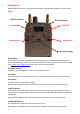
PRODUCT OVERVIEW Upper Panel Headphone Output On/Off/Volume control SMA connector Antenna B SMA connector Antenna A SMA antenna Connector A and B MPR30-IEM is supplied with a couple of antennas. According to the working band, different antenna models can be supply. All the models have Antenna Code label black cap and a black label with code in white colour. For more details see the section Accessories and Parts Headphone Output The audio headphone output with 3.5 mm stereo jack socket lockable (TRS).
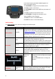
Front panel MPR30-IEM allows an easy and quick configuration using buttons, RGB LED’s and an OLED display. ON Led Indicator SCAN/DOWN Button MENU/SELECT Button RF Led Indicator SYNC/UP MENU/EXIT Button Infrared Interface (IR) OLED Display The receiver has a high contrast display. Pushing one of the 4 buttons while the receiver is active (but the display is off), turn on automatically the display. After a time-out user setting (see Display>Off timeout menu) the display turns off automatically.
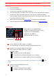
charging status battery status Tuning phase power up ON & RF Led Indicators (Firmware rel. v0.
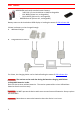
PUTTING THE DIVERSITY RECEIVER INTO OPERATION Insert the batteries Connect the headphones Connect the 2 antennas on the SMA connectors Turn the knob control clockwise until it clicks and verify on the display the Antenna model to use (if the connected antennas on the receiver is different from the antenna model indicate on the display, power off the receiver and replace them with the proper model of antennas) after the power up phase, the Status display is showed on the OLED display verify the
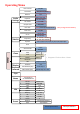
Operating Menu Lock volume Out mode Balance Audio Settings Equalizer L|R Low (-12÷+12) Hi (-12÷+12) Vol. boost 0÷+12dB Output load 32Ω/16Ω Pwr limit Pilot tone Gr-Ch Edit RX Yes/No Mix/Stereo/Mono Frequency Squelch OFF*/100mW/50mW/30mW *Only using lithium battery Yes/No GR (0÷39) CH (0÷59) N: 470.000÷700.000 M: 566.000÷798.000 OFF-0/3/6/9/12/15/18/21/24//28/32/36/40/46 dBµV Scan Arrow mode Clone Add 00÷23 Load default/0/...
From Status Display push SEL and EXIT together to enter on the Main menu Use UP/DOWN to navigate on all available menus Push SEL to select a menu item Use UP/DOWN to move on the different parameters of the menu Push SEL to modify the parameter menu Use UP/DOWN to change the parameter value Keep push SEL to save changing Push EXIT to return on the Main Menu Push EXIT to return on the Status display Audio settings The Audio settings menu allows to configure the audio output.
Equalizer Vol. boost Output load Pwr limit Pilot tone This menu allows to of adjusting the gain of low and high frequency components (bass and treble) within the audio signal. 1. Push UP/DOWN button to Low and High increase/decrease the gain of frequencies the Low frequencies (50Hz) -12dB/+12dB 2. Push SEL button to shift on 1dB steps High frequencies, 3. Push UP/DOWN button to increase/decrease the gain of the High frequencies (10kHz) 4.
Edit RX The Edit RX menu allows to configure the radio frequency settings. PARAMETER Gr-Ch Frequency Squelch Scan SETTING MEANING 0÷39 groups Select current group and channel. Group name and 0÷59 channels channel frequency are displayed on the right. 470÷700 MHz If the specific group/channel is not locked, the for MPR30-IEM-N frequency can be edited in this menu.
Clone The Clone menu allows to configure the quick menu and to manage the Clone setting. PARAMETER SETTING Arrow mode Bal/Mix or Clone Add Load Delete Delete all Clone management MEANING The quick menu is displayed pushing UP or DOWN buttons when the receiver is on the Status display. Set to Bal/Mix to enter quickly to the Balance/Mix mode menu (according to the Out mode configured). Set to Clone to enter quickly on the clone management.
How to load a clone Use Clone>Load menu or UP/DOWN button (if the quick menu is configured to clone) to load a clone. Afterwards push the arrows to change clone, SEL to activeted the clone and EXIT to exit without changing. Ex. The configuration saved before the loading of the clone is saved on the clone named “default”, therefore loading the default “clone” allows to return with the previous settings. The following arrows displayed near the clone number indicates the currently clone loaded.
Display This menu allows to configure display setting PARAMETER LED Contrast Low timeout (sec) Off timeout (sec) SETTING Full Alarm OFF MEANING 3 LED setting are available: Full: LED indicators works normally Alarm: LED indicators lights up only when an alarm happened OFF: LED indicators remain off 0÷5 Change contrast display from 0 (min) to 5 (max). 5÷60 (5sec. steps) 10÷120 (10sec. steps) / OFF Low timeout sets the timeout from 5 to 60 seconds (5sec steps) to decrease the brightness display.
Name menu The name menu allows to change the name of the receiver (12 case-sensitive alphanumeric characters). This is the name displayed in the top of the Status display and it is the name sent to the transmitter with the sync function (for the transmitter with this advanced capability). Use the UP/DOWN buttons to change the selected character and push SEL button to switch to the next character.
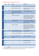
ERROR LIST When an error occurs, the receiver A. shows a message on the display and for some error types B. C. increases the errors counter in the info menu inserts the error type and code on the error list in the info menu When the error is solved, the message on the display disappear, but the error information (code and description) are available on the error list in the Info menu (only for some error, see the below table).
TROUBLESHOOTING Problem “HW init failed” message appears on the display “Battery Low” message appears on the display “Battery charge failed” message appears on the display “I2C communication error” message appears on the display “Device ID copy1 invalid Memory recovered” message appears on the display “Device ID copy2 invalid Memory recovered” message appears on the display “RF copy1 invalid Memory recovered” message appears on the display “RF copy2 invalid Memory recovered” message appears on the display T
The frequencies of all the channels and groups is equal to the lower frequency of the receiver Error in the channel memory during the initialization phase.
TECHNICAL SPECIFICATIONS • Frequency ranges • Switchable channels • Switching-window • Frequencies • Frequency error • Temperature range • Modulation • Nominal deviation • “A” / “B” antenna in • Antenna input imp. • Sensitivity • Co-channel rejection • Adjacent chan. Sel. • Spurious rec. Rej. • IF image rejection • Intermod.
MECHANICAL DRAWING Note: unit is mm 20
21
ITALY ONLY Obblighi di informazione agli utilizzatori Modello di informazioni agli utenti dei prodotti di tipo “professionale” INFORMAZIONE AGLI UTENTI ai sensi dell’art. 13 del Decreto Legislativo 25 luglio 2005, n.
Wireless System Communications Via Spin 156 I-36060 Romano d’Ezzelino Italy Tel. +39 -0424 -382605 Fax +39 - 0424 - 382733 www.wisycom.com e-mail: sales@wisycom.