G AS C OOKTOPS I NSTALLATION I NSTRUCTIONS
As you follow these instructions, you will notice WARNING and CAUTION symbols. This blocked information is important for the safe and efficient installation of Wolf equipment. There are two types of potential hazards that may occur during installation. signals a situation where minor injury or product damage may occur if you do not follow instructions. states a hazard that may cause serious injury or death if precautions are not followed.
W O L F G A S C O O K TO P S I N S TA L L AT I O N R E Q U I R E M E N T S IMPORTANT NOTE: This installation must be completed by a qualified installer, service agency or gas supplier. IMPORTANT NOTE: Save these Installation Instructions for the local inspector’s use. Please read the entire Installation Instructions prior to installation. Installer: please retain these instructions for local inspector’s reference, then leave them with the homeowner.
W O L F G A S C O O K TO P S B E F O R E YO U S TA RT Proper installation is your responsibility. Have a qualified technician install this cooktop. You must also assure that electrical installation is adequate and in compliance with all local codes and ordinances. Wolf gas cooktops are manufactured for use with natural gas or LP gas. Please check product rating plate for type of gas needed. Proper gas supply connection must be available; refer to Gas Supply Requirements on page 10.
I N S TA L L AT I O N I N S T R U C T I O N S S I T E P R E PA R AT I O N C O U N T E R T O P C U T- O U T D I M E N S I O N S L O C AT I O N R E Q U I R E M E N T S IMPORTANT NOTE: Countertop opening dimensions shown on the following pages must be used. The dimensions shown provide for required clearances. Illustrations on the following pages provide the overall dimensions, countertop cut-out and installation specifications for Wolf gas cooktops.
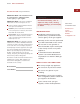
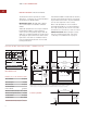
W O L F G A S C O O K TO P S I N S TA L L AT I O N S P E C I F I C A T I O N S The illustrations below provide the overall dimensions, countertop cut-out and installation specifications for Model CT15G. IMPORTANT NOTE: When multiple cooktop units are installed side by side, refer to the countertop cut-out dimensions on page 9. For Model CT15G, the gas service may be supplied through the floor if the cooktop is not installed above an oven.
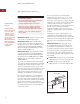
I N S TA L L AT I O N I N S T R U C T I O N S I N S TA L L AT I O N S P E C I F I C A T I O N S If the Model CT30G is installed above cabinets, the gas and electrical placement is not critical. A grounded outlet needs to be placed within 4' (1.2 m) of the right rear of the cooktop. The illustrations below provide the overall dimensions, countertop cut-out and installation specifications for Model CT30G. IMPORTANT NOTE: 33" (838) wide cabinets are recommended for installation of Model CT30G.
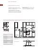
W O L F G A S C O O K TO P S I N S TA L L AT I O N S P E C I F I C A T I O N S The illustrations below provide the overall dimensions, countertop cut-out and installation specifications for Model CT36G. IMPORTANT NOTE: 39" (991) wide cabinets are recommended for installation of Model CT36G. A Wolf 36" (914) built-in oven may be installed below Model CT36G.
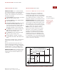
I N S TA L L AT I O N I N S T R U C T I O N S V E N T I L AT I O N O P T I O N S I N S TA L L AT I O N O P T I O N S IMPORTANT NOTE: It is recommended that you operate the Wolf gas cooktop with either a Wolf cooktop ventilation hood, downdraft system or Pro ventilation hood. Contact your Wolf dealer for details. M U LT I P L E C O O K T O P I N S T A L L A T I O N Cooktop Wall Hood – 30" (762) or 36" (914) widths in classic stainless steel.
W O L F G A S C O O K TO P S G A S S U P P LY R E Q U I R E M E N T S EXPLOSION HAZARD — Use a new CSA approved gas supply line and install a gas shut-off valve. I M P O R TA N T N OT E This installation must conform with local codes and ordinances. In the absence of local codes, installations must conform with the American National Standard, National Fuel Gas Code and National Electrical Code regulations. Securely tighten all gas connections.
I N S TA L L AT I O N I N S T R U C T I O N S G A S S U P P LY R E Q U I R E M E N T S LINE PRESSURE TESTING Testing above 1/2 psi (3.5 kPa) 14" (34.9 mb) WC (gauge): The cooktop and its individual shut-off valve must be disconnected from the gas supply piping system during any pressure testing of that system at test pressures greater than 1/2 psi (3.5 kPa). Testing below 1/2 psi (3.5 kPa) 14" (34.
W O L F G A S C O O K TO P S C O O K T O P I N S TA L L AT I O N Remove the cooktop, pressure regulator, burner grates and burner caps from the shipping package. P R E S S U R E R E G U L AT O R Lower the cooktop into the countertop cut-out opening. Center the cooktop in the opening and check that the front edge of cooktop is parallel to the front edge of the countertop. Check that all required clearances are met. Use a pencil to outline the rear edge of the cooktop on the countertop.
I N S TA L L AT I O N I N S T R U C T I O N S C O O K T O P I N S TA L L AT I O N S U R FAC E B U R N E R S G A S S U P P LY L I N E C O N N E C T I O N INITIAL LIGHTING Assemble the flexible metal connector from the gas supply pipe to the pressure regulator. You will need to determine the fittings required, depending on the size of your gas supply line, flexible metal connector and shutoff valve. Refer to the illustration below. The surface burners use electronic igniters in place of standing pilots.
W O L F G A S C O O K TO P S C O O K TO P R E M O V A L C O N TA C T I N F O R M AT I O N Wolf Customer Service: 800-332-9513 Website: wolfappliance.com If it is necessary to remove the cooktop for cleaning or service, shut off the gas supply. Disconnect the gas and electric supply. Remove the mounting brackets on the right and left side of the burner box and remove the cooktop. Reinstall in the reverse order and check the gas connection for leaks.
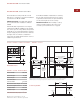
I N S TA L L AT I O N I N S T R U C T I O N S WIRING D I AG R A M S R SPARK MODULE 3 CONDUCTOR POWER CORD WHITE N A 1 1 2 2 WHITE BLK GRN BLACK WHITE RED WHITE N A F SPARK MODULE RED WHITE REAR WHITE BLK Model CT15G FRONT LR SPARK MODULE RR SPARK MODULE N 3 CONDUCTOR POWER CORD A IGN WHITE WHITE N A IGN 1 1 2 2 BLK GRN RED RED BLACK RED WHITE WHITE N N A IGN A IGN RED RED LF SPARK MODULE RF SPARK MODULE RED WHITE WHITE BLK BLK LEFT REAR BLK RIGHT REAR WHITE
W O L F A P P L I A N C E C O M PA N Y, I N C. 8 0 7 6 0 5 R E V- B 10 / 2006 P. O. B OX 4 4 8 4 8 MADISON, WI 53744 800-332-9513 W O L FA P P L I A N C E .