
Inc GAS COOK TOPS INSTALLATION INSTRUCTIONS
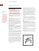


COOKTOP INSTALLATION
Remove the cooktop, pressure regulator,
burner grates and burner caps from the
s
hipping package.
L
ower the cooktop into the countertop cut-out
opening. Center the cooktop in the opening
and check that the front edge of cooktop is
p
arallel to the front edge of the countertop.
Check that all required clearances are met. Use
a pencil to outline the rear edge of the cooktop
on the countertop. Remove the cooktop from
the countertop opening.
IMPORTANT NOTE:
When repositioning the
cooktop in the countertop cut-out opening, lift
the entire cooktop up from the opening to
prevent scratching the countertop.
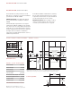
Remove the foam strip from the hardware
package. Apply the foam strip around the
bottom of the burner box flush with the edge
as shown in the illustration below.
Reinsert the cooktop into the countertop
opening. Check that the cooktop is parallel to
the front edge of the countertop. Lift the entire
cooktop to make adjustments and align the
rear edge with the pencil line.
Attach the brackets to the burner box. Insert
the 3
1
/2" (89) clamping screws into the
brackets. Use a screwdriver to tighten the
clamping screws against the underside of the
countertop. Refer to the illustration below. Do
not over
tighten screws.
12
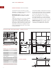
PRESSURE REGULATOR
I
nstall the pressure regulator with the arrow on
the regulator pointing up toward the unit and
in a position where you can reach the access
c
ap. Refer to the illustration below.
IMPORTANT NOTE:
All connections must be
wrench-tightened. Do not make connections to
the gas regulator too tight, as this may crack
the regulator and cause a gas leak. Do not
allow the regulator to turn on the pipe when
tightening fittings.
Cooktop
Burner Box
Foam
Strip
3
1
/2" (89)
Clamping
Screw
Burner Box
Countertop
Bracket
Screws
Bracket
Foam strip application Bracket installation
WOLF GAS COOKTOPS
Rear of
Cooktop
Pressure
Regulator
Access
Cap
Gas Flow –
Arrow
Points Up
Pressure regulator