
Operation Manual

8
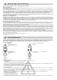
Safety instructions
Operating times
Please check noise abatement regulations prevailing in your country.
• Check the operating tool for
a) tight t of the attachment parts
b) damage or heavy wear and tear - When replacing observe installation instructions
•
Examine line installed on the outside of the tool and the connection cable for damage and wear and tear (brittleness). Only use when no damages can be found.
• Repairs to the cable may only be carried out by a specialist.
• Check the grassbox more often for wear and tear.
• Before adjusting or cleaning of the tool or before checking whether the connection line has been knotted up or damaged switch off the tool and
pull plug out of the socket.
3. Cable
• Please work with safety cables from WOLF. For the connection only lines which are not lighter than rubber hose lines H0 7 RN-F with a minimum
diameter of 3 x 1,5 mm
2
must be used.
• The attachments of the connection cables must be rubber or covered with rubber and comply with Standard DIN/VDE 0620.
• Attachments must be splashproof (applicable in Austria only).
• Use a leakage-protective system (RCD) with a leakage current of no more than 30 mA.
• Attach connection cable to traction relief. Make sure that in does not rub against edges, pointed or sharp objects. Do not squeeze cable through
door or window gaps.
• Switching devices must not be removed or bridged (e. g. tying of switching lever to guide spar).
4. Starting up
• Only switch on motor when your feet are at a safe distance from the cutting tools.
• Do not tilt the aeriator when operating the switch unless absolutely necessary. If it is necessary tilt the aeriator as little as possible and always in
such a way that the aeriator remains between you and the blade.
5. During aeriation - for your safety
• Warning, Danger! Cutting tool is lagging!
• Adhere to the safety distance given by the guidance spars.
• Only switch on motor when your feet are at a safe distance from the cutting tools.
• Always make sure that you have a safe footing, especially on slopes. Never run, always walk slowly.
• Do not use the aeriator on steep slopes.
• Keep cable away from operating tool when aeriating.
• Always move aeriator horizontally to the slope, never up and down.
• Switch off aeriator when tilting or transporting.
• Never use the aeriator when protective devices or housing parts are damaged or missing.
• Before lifting or removing the aeriator switch off motor an wait until the operating tools have come to a complete standstill.
• Before removing the grassbox or adjusting of the operating height switch off motor and wait for the complete standstill of the operating tools.
• Replace worn or damaged blades as a complete set. Observe installation instructions. For safety reasons always use original spare parts.
•
Maintenance and cleaning procedures on the aeriator as well as removing the protective devices may only be carried out when the engine is switched off.
• Never store the aeriator in damp surroundings or near open ame.
• Should have run over an object with the aeriator it should be examined by a specialist (see list of repair shops) for safety reasons.
• If the connection cable is damaged during use it must be disconnected immediately. Do not touch the cable until it is disconnected.
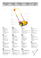
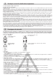
Assembly
Assembling bottom handle part (fig. M1)
Insert securing screw (A) from inside through the left side element, so that both projections catch in the recesses (1). Position
insulation element (B) from outside; the two nubs must catch in the holes of the side element (2). Position handle element (M) in
the insulating element (B). Place insulating element (C) so that the large opening points to the outside. Then press washer (D) into
the opening of the insulating element (C) and tighten wing nut (G).
Assemble the right handle element in the same order.
Assembling top of handle (fig. M2)
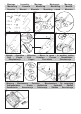
Attaching switch, strain relief and clips (fig. M3)
Fold up switch bracket (1) and position switch (H) on the upper handle element so that the two nubs catch in the holes (2). Close
switch bracket (1) and insert cable strain relief (I). Then fasten switch (H) and cable strain relief (I) with the two screws (K). Fasten
switch cable (3) with the clips (L) on the handle rod.
Attaching protective flap (fig. M4)
Place protective flap (O) on the cover (1). Then press retainer slots (2) into the fastening flaps (3) on the cover (1).
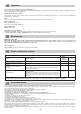
Operation
Lawn condition Working position
Transport / uneven lawn surface 1
Clean lawn surface 2
Worn blade 3
Setting the working depth (Fig. B1)
The working depth is adjustable to 3 heights (1 = 3 mm, 2 = -3 mm, 3 = -9 mm). Pull adjustment arm (A) away from side cover and
allow to catch in desired position (B). Adjust the height alternately left and right by only 1 position. The adjustment arms must always
be in the same height position.
Recommended working depths
(Fig. B1)