E Series Oven Installation Guide SPECIFICATIONS, INSTALLATION, AND MORE
E Series Oven E Series Oven Contents Important Note 2 Important Note 3 Product Information 4 Specifications 12 Installation To make sure this product is installed and operated safely and efficiently, take note of the following types of highlighted information throughout this guide: IMPORTANT NOTE: Highlights information that is especially important. CAUTION Indicates a situation where minor injury or product damage may occur if instructions are not followed.
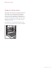
E Series Oven Product Information Important product information, including the model and serial number, are listed on the product rating plate. If service is necessary, contact Wolf Factory Certified Service with the model number and serial number. For the name of the nearest Wolf Factory Certified Service or for questions regarding the installation, visit the Product Support section of our website, or call Wolf Customer Care at 800-222-7820. The rating plate is located near the bottom trim on the left.
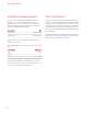
Specifications Installation Requirements Dual Installation The oven can be installed in a standard or flush inset application. If a cooktop is installed above an oven, a minimum of 1/4" (6) is required between the units. The location of the electrical supply within the oven opening may require additional cabinet depth. Two 30" single ovens can be installed side by side in a standard or flush inset application. A dual installation kit is required.
Specifications Electrical Requirements Installation must comply with all applicable electrical codes. Locate the electrical supply flush with the back wall and within the shaded area shown in the illustrations on pages 6-11. For ease of installation, the electrical supply for the oven can be placed in an adjacent cabinet within reach of the conduit. Performance may be compromised if the electrical supply is less than 240 volts.
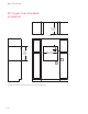
Specifications 30" Single Oven Standard Installation 23 1/4" (591) OPENING DEPTH TOP VIEW 5" (127) E 4" 27 1/2" (699) OPENING HEIGHT (102) 28 1/2" (724) OPENING WIDTH E E SIDE VIEW NOTE: Location of electrical supply within opening may require additional cabinet depth.
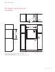
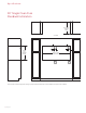
Specifications 30" Single Oven Flush Inset Installation 7/8" (22) 24" (610) FLUSH INSET DEPTH FINISHED CLEATS* TOP VIEW 30 1/8" (765) FLUSH INSET WIDTH** 5" 11/8" (29) (127) E 4" (102) 28 3/4" (730) FLUSH INSET HEIGHT** 13/16" (21) E 1/8" (3) SIDE VIEW E FRONT VIEW *Shaded areas will be visible and should be finished to match cabinetry. **Dimension provides minimum reveals. NOTE: Location of electrical supply within opening may require additional cabinet depth. wolfappliance.
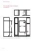
Specifications 30" Double Oven Standard Installation 23 1/4" (591) OPENING DEPTH TOP VIEW 5" (127) E 4" (102) 49 7/8" (1267) OPENING HEIGHT 28 1/2" (724) OPENING WIDTH E E 17" (432) TYPICAL SIDE VIEW NOTE: Location of electrical supply within opening may require additional cabinet depth.
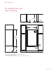
Specifications 30" Double Oven Flush Inset Installation 7/8" (22) 24" (610) FLUSH INSET DEPTH FINISHED CLEATS* TOP VIEW 30 1/8" (765) FLUSH INSET WIDTH** 5" 11/8" (29) (127) E 4" (102) 51 1/8" (1299) FLUSH INSET HEIGHT** 13/16" (21) E 1/8" (3) E 17" (432) TYPICAL SIDE VIEW FRONT VIEW *Shaded areas will be visible and should be finished to match cabinetry. **Dimension provides minimum reveals. NOTE: Location of electrical supply within opening may require additional cabinet depth.
Specifications 30" Single Oven Dual Standard Installation 23 1/4" (591) OPENING DEPTH TOP VIEW 5" (127) 27 1/2" (699) OPENING HEIGHT E 5" (127) 4" 4" (102) (102) 58 1/2" (1486) OPENING WIDTH E SIDE VIEW FRONT VIEW NOTE: Location of electrical supply within opening may require additional cabinet depth. A dual installation kit is required for this installation.
Specifications 30" Single Oven Dual Flush Inset Installation 24" (610) FLUSH INSET DEPTH 7/8" (22) FINISHED CLEATS* TOP VIEW 60 1/8" (1527) FLUSH INSET WIDTH** 11/8" (29) 28 3/4" 5" (127) E 5" (127) E 4" 4" (102) (102) E E (730) FLUSH INSET HEIGHT** 13/16" (21) 1/8" (3) SIDE VIEW FRONT VIEW *1" (25) minimum depth. Shaded areas will be visible and should be finished to match cabinetry. ** Dimension provides minimum reveals.
Installation Preparation Electrical Connection WARNING Before moving the oven, protect any finished flooring and secure the oven door(s) closed to prevent damage. Use an appliance dolly to move the oven near the opening. Place the appliance dolly on the side or back to prevent damage. Remove and recycle packing materials. Do not lift or carry the oven by the door handle. Oven Door Removal Verify that power is disconnected from the electrical box before proceeding.
Installation Door Alignment Troubleshooting To adjust the door, loosen the nuts on both sides of the door, manually adjust the bottom of the door side to side, and tighten the nuts. IMPORTANT NOTE: If the range does not operate properly, follow these troubleshooting steps: • Verify electrical power is supplied to the oven. • Verify proper electrical connections. • If the oven does not operate properly, contact Wolf Factory Certified Service. Do not attempt to repair the oven.
Horno de la serie E Horno de la serie E Contenido Aviso importante 14 Aviso importante 15 Información del producto 16 Especificaciones 24 Instalación Para asegurarse de que este producto se instale y opere de forma segura y eficiente, tome nota de los siguientes tipos de información resaltada en este manual: NOTA IMPORTANTE:: Señala la información que es especialmente importante.
Horno de la serie E Información del producto La información importante del producto, incluidos el modelo y el número de serie de la unidad, se encuentra en la placa de datos del producto. Si es necesario realizar algún servicio, póngase en contacto con el servicio certificado de fábrica de Wolf y tenga a mano el número de modelo y el número de serie.
Especificaciones Requisitos de instalación Instalación doble El horno se puede instalar en una aplicación estándar o empotrable. Si se instala una estufa sobre un horno, se requiere un espacio mínimo de 1/4" (6) entre las unidades. Es posible que la ubicación del suministro eléctrico al interior de la abertura del horno requiera de un gabinete de mayor profundidad. Se pueden instalar dos hornos sencillos de 30”, uno al lado del otro, en una aplicación estándar o empotrable.
Especificaciones Requisitos eléctricos REQUISITOS ELÉCTRICOS- Horno sencillo Suministro eléctrico Servicio Con conexión a tierra, 240/208 V CA, 60Hz Circuito dedicado de 30 amperes Conducto 4' (1.2 m) Total de amperes 22 Carga máxima conectada 5.4 kW REQUISITOS ELÉCTRICOS- Horno doble Suministro eléctrico Servicio Conducto Total de amperes Carga máxima conectada Con conexión a tierra, 240/208 V CA, 60Hz Circuito dedicado de 50 amperes 5' (1.5 m) 45 10.8 kW wolfappliance.
Especificaciones Instalación estándar de horno sencillo de 30” 23 1/4" (591) PROFUNDIDAD DE LA ABERTURA VISTA SUPERIOR 5" E (127) 4" 27 1/2" (699) ALTURA DE LA ABERTURA (102) 28 1/2" (724) ANCHO DE LA ABERTURA E E VISTA LATERAL VISTA FRONTAL NOTA: es posible que la ubicación del suministro eléctrico al interior de la abertura requiera de un gabinete de mayor profundidad.
Especificaciones Instalación empotrable de horno sencillo de 30” 24" (610) PROFUNDIDAD DE LA INSTALACIÓN 7/8" (22) EMPOTRABLE CORNAMUSAS TERMINADAS* VISTA SUPERIOR 30 1/8" (765) ANCHO DE LA INSTALACIÓN EMPOTRABLE** 28 3/4" 5" 11/8" (29) (127) E 4" (102) (730) ALTURA DE LA INSTALACIÓN EMPOTRABLE** 13/16" (21) E 1/8" (3) VISTA LATERAL E VISTA FRONTAL *Las áreas sombreadas serán visibles y se les debe dar un acabado que combine con los gabinetes. **La dimensión especifica los márgenes mínimos.
Especificaciones Instalación estándar de horno doble de 30” 23 1/4" (591) PROFUNDIDAD DE LA ABERTURA VISTA SUPERIOR 5" E (127) 4" (102) 49 7/8" (1267) ALTURA DE LA ABERTURA 28 1/2" (724) ANCHO DE LA ABERTURA E E 17" (432) TÍPICO VISTA LATERAL VISTA FRONTAL NOTA: es posible que la ubicación del suministro eléctrico al interior de la abertura requiera de un gabinete de mayor profundidad.
Especificaciones Instalación empotrable de horno doble de 30” 24" (610) PROFUNDIDAD DE LA INSTALACIÓN 7/8" (22) EMPOTRABLE CORNAMUSAS TERMINADAS* VISTA SUPERIOR 30 1/8" (765) ANCHO DE LA INSTALACIÓN EMPOTRABLE** 5" 11/8" (29) (127) E 4" (102) 51 1/8" (1299) ALTURA DE LA INSTALACIÓN EMPOTRABLE** 13/16" (21) E 1/8" (3) E 17" (432) TÍPICO VISTA LATERAL VISTA FRONTAL *Las áreas sombreadas serán visibles y se les debe dar un acabado que combine con los gabinetes.
Especificaciones Instalación dual estándar de horno sencillo de 30” 23 1/4" (591) PROFUNDIDAD DE LA ABERTURA VISTA SUPERIOR 5" (127) 27 1/2" (699) ALTURA DE LA ABERTURA E 4" 4" (102) 58 1/2" (1486) ANCHO DE LA ABERTURA VISTA FRONTAL NOTA: es posible que la ubicación del suministro eléctrico al interior de la abertura requiera de un gabinete de mayor profundidad. Para esta instalación se requiere un kit de instalación doble.
Especificaciones Instalación dual empotrable de horno sencillo de 30” 24" (610) PROFUNDIDAD DE LA INSTALACIÓN EMPOTRABLE 7/8" (22) CORNAMUSAS TERMINADAS* VISTA SUPERIOR 60 1/8" (1527) ANCHO DE LA INSTALACIÓN EMPOTRABLE** 11/8" (29) 5" (127) E 4" 28 3/4" 5" (127) E 4" (102) (102) E E (730) ALTURA DE LA INSTALACIÓN EMPOTRABLE** 13/16" (21) 1/8" (3) VISTA LATERAL VISTA FRONTAL *1" (25) profundidad mínima.
Instalación Preparación Conexión eléctrica ADVERTENCIA Antes de mover el horno, proteja cualquier suelo acabado y asegúrese de que la puerta o puertas del horno estén cerradas para que no se dañen. Use una plataforma móvil para mover el horno cerca de la abertura. Para evitar daños, coloque la carretilla del electrodoméstico en el costado o en la parte posterior. Retire y recicle los materiales de embalaje. No utilice la manija de la puerta del horno para levantarlo ni transportarlo.
Instalación Alineamiento de la puerta Solución de problemas Para ajustar la puerta, afloje las tuercas en ambos lados de la puerta, ajuste manualmente la parte inferior de la puerta de lado a lado, y apriete las tuercas. NOTA IMPORTANTE:: Si la estufa no funciona correctamente, siga estos pasos para resolver los problemas: TUERCA • Compruebe que el horno tenga corriente eléctrica. • Compruebe que las conexiones eléctricas estén correctas.
Four de la série E Four de la série E Table des matières Remarque importante 26 Remarque importante 27 Renseignements sur le produit 28 Spécifications Pour s'assurer que ce produit est installé et utilisé en toute sécurité et aussi efficacement que possible, prenez note des types de renseignement mis en évidence tout au long de ce guide : 36 Installation REMARQUE IMPORTANTE: Met en évidence des renseignements qui sont particulièrement importants.
Four de la série E Renseignements sur le produit Des renseignements importants sur le produit, y compris les numéros de modèle et de série, se trouvent sur la plaque signalétique du produit. Si vous avez besoin de service, communiquez avec le service Wolf certifié par l’usine avec les numéros de modèle et de série.
Spécifications Exigences d’installation Installation double Le four peut être installé dans une application standard ou à affleurement. Si la surface de cuisson est installée audessus d'un four, un espace minimum de 1/4 po (6) est requis entre les unités. L'emplacement de l'alimentation électrique dans l'ouverture du four peut exiger une profondeur d'armoire supplémentaire. Deux fours simples de 30 po peuvent être installés un à côté de l'autre dans une application standard ou à affleurement.
Spécifications Exigences électriques EXIGENCES ÉLECTRIQUES - four simple Alimentation électrique Service mise à la terre, 240/208 volts CA, 60Hz circuit dédié de 30 ampères Canalisation 4 pi (1,2 m) Intensité électrique 22 ampères Charge max. de connexion 5,4 kW EXIGENCES ÉLECTRIQUES - four double Alimentation électrique Service Canalisation Intensité électrique Charge max.
Spécifications Installation standard d'un four simple 30 po (762) 23 1/4 po (591) PROFONDEUR D’OUVERTURE VUE DE DESSUS 5 po E (127) 4 po 27 1/2 po (699) HAUTEUR DE L’OUVERTURE (102) 28 1/2 po (724) LARGEUR DE L’OUVERTURE E E VUE DE PROFIL VUE DE FACE REMARQUE : L’emplacement de l’alimentation électrique dans l’ouverture peut exiger une profondeur d’armoire supplémentaire.
Spécifications Installation à affleurement d'un four simple 30 po (762) PROFONDEUR D’AFFLEUREMENT 7/8 po (22) DE 24 po (610) TAQUETS FINIS* VUE DE DESSUS LARGEUR D’AFFLEUREMENT DE 30 1/8 po (765)** 5 po 11/8 po (29) (127) E 4 po (102) HAUTEUR D’AFFLEUREMENT DE 28 3/4 po (730)** 13/16 po (21) 1/8 VUE DE PROFIL po (3) E E VUE DE FACE *Les zones ombragées seront visibles et doivent être finies pour s’agencer avec les armoires. **La dimension fournit des jeux minimums.
Spécifications Installation standard d'un four double de 30 po (762) PROFONDEUR D’OUVERTURE DE 23 1/4 po (591) VUE DE DESSUS 5 po E (127) 4 po (102) HAUTEUR DE L’OUVERTURE DE 49 7/8 po (1 267) LARGEUR DE L’OUVERTURE DE 28 1/2 po (724) E E 17 po (432) TYPIQUE VUE DE PROFIL VUE DE FACE REMARQUE : L’emplacement de l’alimentation électrique dans l’ouverture peut exiger une profondeur d’armoire supplémentaire.
Spécifications Installation à affleurement d'un four double de 30 po (762) 7/8 PROFONDEUR D'AFFLEUREMENT po (22) DE 24 po (610) TAQUETS FINIS* VUE DE DESSUS LARGEUR D'AFFLEUREMENT DE 30 1/8 po (765)** 5 po 11/8 po (29) (127) E 4 po (102) HAUTEUR D’AFFLEUREMENT DE 51 1/8 po (1 299)** 13/16 po (21) 1/8 po (3) E E 17 po (432) TYPIQUE VUE DE PROFIL VUE DE FACE *Les zones ombragées seront visibles et doivent être finies pour s’agencer avec les armoires. **La dimension fournit des jeux minimums.
Spécifications Installation standard double d'un four simple 30 po (762) PROFONDEUR D’OUVERTURE DE 23 1/4 po (591) VUE DE DESSUS 5 po E (127) HAUTEUR DE L’OUVERTURE DE 27 1/2 po (699) 4 po 4 po (102) (102) LARGEUR DE L’OUVERTURE DE 58 1/2 po (1 486) E VUE DE PROFIL VUE DE FACE REMARQUE : L’emplacement de l’alimentation électrique dans l’ouverture peut exiger une profondeur d’armoire supplémentaire. Une trousse d’installation double est requise pour cette installation.
Spécifications Installation double à affleurement d'un four simple 30 po (762) 7/8 PROFONDEUR D'AFFLEUREMENT DE 24 po (610) po (22) TAQUETS FINIS* VUE DE DESSUS LARGEUR D’AFFLEUREMENT DE 60 1/8 po (1 527)** 5 po 11/8 po (29) (127) E 4" 5 po E (127) 4 po (102) (102) E E HAUTEUR D’AFFLEUREMENT DE 28 3/4 po (730)** 13/16 po (21) 1/8 VUE DE PROFIL po (3) VUE DE FACE *Profondeur minimale de 1Êpo (25).
Installation Préparation Connexion électrique AVERTISSEMENT Avant de déplacer le four, protégez tout plancher fini et fixez la (les) porte(s) du four en position fermée pour éviter tout dommage. Utilisez un chariot à appareil pour déplacer le four près de l'ouverture. Placez le chariot à appareil sur le côté et l’arrière pour éviter tout dommage. Retirez et recyclez les matériaux d’emballage. Ne soulevez pas et ne transportez pas le four par la poignée de porte.
Installation Alignement de la porte Dépannage Pour ajuster la porte, desserrez les écrous des deux côtés de la porte, ajustez manuellement le bas de la porte d'un côté à l'autre, puis serrez les écrous. REMARQUE IMPORTANTE: Si la cuisinière ne fonctionne pas correctement, suivez les étapes de dépannage suivantes : ÉCROU • Vérifiez l'alimentation électrique du four. • Vérifiez les connexions électriques.
WOLF APPLIANCE, INC. P.O. BOX 44848 MADISON, WI 53744 9028912 REV-B 09/2020 WOLFAPPLIANCE.COM 800.222.