
Company Brush Cutter User Manual


34 Dealer Service
MAN0963 (2/16/2012)
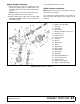
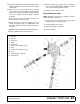
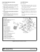
SPLITTER GEARBOX REPAIR - STYLE B
Refer to Figure 16, page 35.
See pages 60 and 61 to determine gearbox style. Style
"A" has removable shaft covers. Style "B" has a top
cover.
Splitter Gearbox Removal from Cutter
1. Disconnect and remove all drivelines from
gearbox.
2. Remove the four cap screw and lock nuts that
secure gearbox to cutter, and remove gearbox.
NOTE: Gearbox is heavy: do not attempt to move it
without mechanical assistance.
Splitter Gearbox Disassembly
Refer to Figure 16.
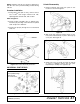
Center Shaft
1. Remove plug from side of gearbox and pour out
the gear oil.
2. Remove seal (3, to be replaced) from the front and
rear of the center shaft (9).
3. Remove snap ring (4) and shim (5) from the front
and rear of the center shaft (9).
4. Support gearbox in a hand press and push on the
rear of the center shaft.
5. Remove bearing (1) from center shaft (9).
6. Remove six cap screws (11) and top cover (10)
from the gearbox housing.
7. Remove gear (8) and bearing (1).
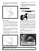
Side Shaft
8. Remove seal (3, to be replaced) from the output
shaft (7).
9. Remove snap ring (4) and shim (5) from front
output shaft (7). Remove snap ring (4) from the
rear of shaft.
10. Support gearbox in hand press. Using a punch
through the front opening of the gearbox and, push
shaft (7) and bearing (1) out the backside of
housing.
11. Remove gear (6) from inside housing.
12. Remove bearing (1) and shim (5) by using a
hammer and punch through front opening of the
gearbox and force them out the backside of the
housing.
13. Repeat steps 7 through 11 for opposite side shaft.
Inspect Components
14. Inspect gears for broken teeth and wear. Some
wear is normal and will show on the loaded side of
the teeth. Forged gear surfaces are rough when
new. Check that wear pattern is smooth.
15. Inspect shafts for grooves, nicks, or bumps in the
areas where seals seat. Resurface any damage
with emery cloth or replace shaft.
16. Inspect housing and caps for cracks or other
damage.
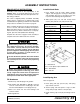
Splitter Gearbox Assembly
Refer to Figure 16.
1. Clean housing, pay specific attention to areas
where gaskets are installed.
2. Wash housing and all components thoroughly.
3. Select a clean work area to assemble gearbox.
4. Replace all seals, bearings, and gaskets.
5. All parts must be clean and lightly oiled before
assembly.
Side Shaft
6. Insert bearing (1) and shim (5) in housing using a
round tube of the same size diameter and a hand
press.
7. Place gear (6) inside the housing and slide output
shaft (7) through gear (6) and into bearing (1).
Secure with snap ring (4).
8. Slide bearing (1) and shim (5) over output shaft.
Secure with snap ring (4).
9. Check end play of shaft by moving it in and out. If
end play is more than 0.012", insert another shim
(8) between snap ring and bearing. Repeat
process until end play is less than 0.012".
10. Check rotational torque. Torque should be less
than 2.2 lbs-inch gear.
11. Place seal (3) over shaft and press into housing
using a tube of the same diameter. Seal should be
flush with housing when properly installed.
12. Repeat steps 6 through 10 for opposite side shaft.
Center Shaft
13. Place gear (8) inside housing and slide center shaft
(9) through the gear from the front of the housing.
14. Slide bearings (1) and shims (5) over each end of
the center shaft (9). Secure bearings into position
using snap rings (4).
15. Check end play of shaft by moving it in and out. If
end play is more than 0.012", insert another shim
(5) between snap ring and bearing. Repeat
process until end play is less than 0.012".
16. Check rotational torque. Torque should be less
than 2.2 lbs-inch gear.