
Company Brush Cutter User Manual


Dealer Service 37
MAN0963 (2/16/2012)
NOTE: Hydraulic jack will not operate if tipped more
than 90°. Use care to prevent bending crossbar during
removal.
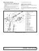
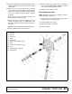
Crossbar Installation
1. Using emery cloth (220 or finer), remove surface
rust, Loctite
®
and foreign material from hub,
splined gearbox vertical shaft, and crossbar.
Refer to Figure 19.
2. Install crossbar assembly (10) on splined shaft.
Install nut (54) and align a slot with hole in splined
shaft. Torque nut to 450 lbs-ft.
3. Install cotter pin (55) through slot in nut and bend
ends over.
Figure 19. Crossbar Assembly Installation
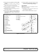
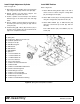
UNIVERSAL JOINT REPAIR
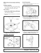
Figure 20. U-Joint Exploded View
U-Joint Disassembly
1. Remove external snap rings from yokes in four
locations as shown in Figure 21.
.
Figure 21.
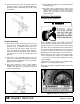
2. With snap rings removed, support drive in vise,
hold yoke in hand and tap on yoke to drive cup up
out of yoke. See Figure 22.
Figure 22.
3. Clamp cup in vise as shown in Figure 23 and tap
on yoke to completely remove cup from yoke.
Repeat Step 2 and Step 3 for opposite cup.
Figure 23.
1. Yoke
2. Cup and bearings
3. Snap ring
4. Journal cross