
Company Brush Cutter User Manual


Assembly 39
MAN0963 (2/16/2012)
ASSEMBLY INSTRUCTIONS
DEALER SET-UP INSTRUCTIONS
Assembly of this cutter is the responsibility of the
WOODS dealer. It should be delivered to the owner
completely assembled, lubricated and adjusted for nor-
mal cutting conditions.
The cutter is shipped partially assembled. Assembly
will be easier if components are aligned and loosely
assembled before tightening hardware. Recommended
torque values for hardware are located on page 82.
Select a suitable working area. A smooth hard surface,
such as concrete, will make assembly much quicker.
Open parts boxes and lay out parts and hardware to
make location easy. Refer to illustrations, accompany-
ing text, parts lists and exploded view drawings.
Complete the check list on page 51 when assembly is
complete and cutter is delivered to the customer.
Before working underneath, carefully read Oper-
ator’s Manual instructions, disconnect driveline,
raise mower, securely block up all corners with
jackstands, and check stability. Secure blocking
prevents equipment from dropping due to hydrau-
lic leak down, hydraulic system failures, or
mechanical component failures.
Do not disconnect hydraulic lines until machine
is securely blocked or placed in lowest position
and system pressure is released by operating
valve levers.
Always wear relatively tight and belted clothing
to avoid entanglement in moving parts. Wear
sturdy, rough-soled work shoes and protective
equipment for eyes, hair, hands, hearing, and head;
and respirator or filter mask where appropriate.
Fill Gearboxes
1. Remove top and side plugs from gearbox.
2. Fill gearbox with SAE 80W or 90W EP oil until it
runs out of side level hole. Install plug in the side
hole and vented dipstick or vent plug in the top.
3. Allow oil to drain into the lower bearings and
recheck oil level.
4. Fill all gearboxes.
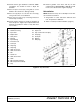
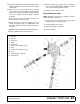
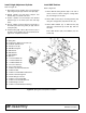
Install Attitude Rods
1. Insert attitude rods (6) under splitter gearbox
support and through pivot casting in wheel yoke
arm assembly. The rod is a very tight fit; use care
to prevent thread damage during installation.
2. Slide spacer (52) over rod and loosely install
washer (107) and two nuts (109) for both rods.
Figure 27. Attitude Rod Installed on Wheel Yoke Tube
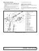
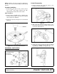
Install Spring Arm
Refer to Figure 28.
1. Place spring arm (43), spacers (53), and spring
(44) on deck as shown.
2. Secure spring arm and spacers to lugs on deck
using clevis pin (55) and two cotter pins (62).
3. Install retaining cap screw (85) and flange lock nut
(88).
CAUTION
Small Aircraft Tires
Attitude Rod Length
Beyond Nuts (34)
Tongue at 11" 3.5
Tongue at 18" 1.75
Large Aircraft Tires
Tongue at 11" 4.5
Tongue at 18" 2.5
6. Attitude Rod
52. 1" x 3.75 Spacer, Pipe Schedule 40
107.1" Flat Washer
109.1" Hex Nut