
Company Brush Cutter User Manual


40 Assembly
MAN0963 (2/16/2012)
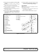
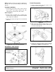
Install Height Adjustment Cylinder
Refer to Figure 28.
1. Attach base end of cylinder (45) to the spring arm
(43) using clevis pin (54) and two cotter pins (62).
2. Extend cylinder rod and place transport lock
bracket (46) over cylinder rod clevis.
3. Position cylinder rod and transport lock bracket
between lugs on the wheel yoke tube and align
holes.
4. Secure cylinder rod and transport lock bracket to
the wheel yoke tube using clevis pin (56) and two
cotter pins (62).
5. Install bushing (90), elbow, (69) and hose (59) to
the base end of cylinder (45). See Install Hose Kit,
page 45 for complete instructions.
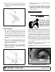
Install SMV Emblem
Refer to Figure 28.
1. Attach SMV mounting bracket (48) to left side of
center section as shown using two carriage bolts
(81) and flange lock nuts (88).
2. Attach SMV socket (49) to mounting bracket (48)
using two carriage bolts (70) and lock nuts (75).
3. Attach SMV emblem (51) to SMV bracket (50)
using two round head cap screws (67) and hex
nuts (68).
Insert SMV bracket (50) and emblem (51) into
socket (49).
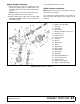
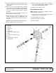
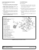
Figure 28. Spring Arm and Cylinder Installation
43. Spring Arm
44. Compression Spring, 3.25 x .69 x 9.5
45. Hydraulic Cylinder 3-1/2
46. Transport Lock-Up
48. SMV Mounting Link
49. SMV Socket
50. SMV Bracket
51. SMV Emblem
53. Spacer, 1"
54. 1 x 2.72 Headless Pin
55. 1 x 4.58 Headless Pin
56. 1 x 5.08 Headless Pin
59. 1/4 x 1/4 x 156 Hose
62. 1/4 x 1-1/2 Cotter Pin
67. 1/4 NC x 1/2 Round Head Screw
68. 1/4 NC Hex Nut
69. 1/4 NPT x 1/4 NPT Elbow w/Restrictor
70. 5/16 NC x 3/4 Carriage Bolt
75. 5/16 NC Flange Lock Nut
81. 1/2 NC x 1-1/2 Carriage Bolt
85. 1/2 NC x 5 Hex Head Cap Screw
88. 1/2 NC Flange Lock Nut
90. 1/2 NPT x 1/4 NPT Reducer Bushing