
Company Brush Cutter User Manual

42 Assembly
MAN0963 (2/16/2012)
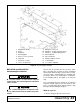
Install 3-Joint Drive (540 RPM Only)
Before installing cutter input driveline to gearbox, check
the tag wired to the driveline and the tag wired to the
input shaft of gearbox. Ensure the tag rpm speeds
match the rpm speed decal on front of cutter. After con-
firming all speeds match, remove and discard tags and
then complete driveline assembly.
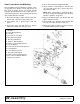
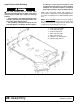
1. Attach H-frame (30) to tongue with cap screw (93),
sleeves (39), cup washers (94), and nut (95).
2. Coat splined end of gearbox input shaft with
grease.
3. Align hole in drive yoke with groove on gearbox
input shaft and slide drive (33) onto shaft.
4. Secure with bolt and nut supplied with drive.
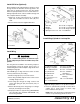
5. Secure driveline carrier bearing to H-frame with
cap screw (86), washer (87), sleeves (89) and a
flanged lock nut (88).
NOTE: When cutting height is established, adjust
the 3-joint H-frame bearing height so that the front
driveline is parallel to the ground.
6. Attach front driveline (32) to rear driveline (33) and
tighten clamp bolt and nut.
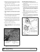
7. Attach shield (19) to driveline carrier bearing with
two cap screws (76) and lock washers (77).
8. Attach spacer (38) to top hole of H-frame using cap
screw (86) and flanged lock nut (88).
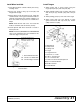
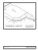
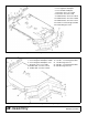
Figure 31. 3-Joint Drive Installation
5. CV Drive
19. Carrier Bearing Shield
30. H-Frame
32. Front 2/3 of 3-Joint Drive
33. Rear Telescoping Shaft
38. .66 x .88 x 4.50 Sleeve
39. .625 x 1 x .563 HT Sleeve
76. 3/8 NC x 1 Hex Head Cap Screw
77. 3/8 Lock Washer
86. 1/2 NC x 6-1/2 Hex Head Cap Screw
87. 1/2 Flat Washer
88. 1/2 NC Flange Lock Nut
89. .50 x 1.00 x 1.031 Sleeve
93. 5/8 NC x 7 Hex Head Cap Screw
94. 5/8 x 1-3/4 x 14 GA Cup Washer
95. 5/8 NC Hex Lock Nut