
Company Brush Cutter User Manual

Assembly 45
MAN0963 (2/16/2012)
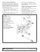
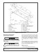
Install Wing Wheel Yoke Adjustment Link
Use a suitable lifting device of sufficient capac-
ity. Use adequate personnel to handle heavy com-
ponents.
1. With a lifting device raise right wing and lock in the
up position using the wing lock-up bar. Leave lifting
device attached for added support.
2. Attach adjustable link (7) to right side of center
wheel yoke arm and secure with cap screw (104)
and lock nut (110).
3. Attach opposite end of adjustable link (7) to wing
wheel yoke arm and secure with cap screw (104)
and lock nut (110).
4. Remove lock-up bar and carefully lower wing using
lifting device.
5. Repeat process for left wing. (BW126XHDR only
has right wing installed; BW126XHDL only has left
wing installed.)
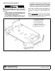
Figure 37. Left Wing Wheel Yoke
Adjustment Link Installed
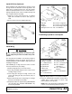
Install Wing Driveline
1. Attach clutch shield (15) to wing gearbox using four
cap screws (113), lock washers (73), and flat
washers (72).
2. Slide non clutch end of driveline (3) over wing
gearbox shaft and align holes with groove.
3. Secure driveline to shaft using cap screws and lock
nuts supplied with driveline.
4. Slide clutch end of driveline over splitter gearbox
and secure using cap screws and lock nuts
supplied with driveline.
5. Repeat process for left driveline. (BW126XHDR
only has right wing installed; BW126XHDL only
has left wing installed.)
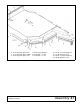
Figure 38. Right Driveline Installation
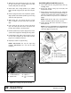
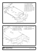
Install Hose Kit
1. Remove plug from rod end of each wing cylinder.
2. With the wings in the down position and cylinder
extended, remove and reinstall the plugs from the
base of the wing cylinders. This will trap air behind
the piston and help when lowering the wings.
3. Install reducer bushing and restricter elbow into
cylinders. Position elbow on center cylinder to point
forward; on wing cylinders point elbows to the
center.
NOTE: Make sure a breather fitting is installed in
the rod end port of the wheel yoke cylinder.
4. Attach hose to each elbow.
CAUTION
7
104
DP2
7. Adjustable link
104. 1 NC x 4-1/2 HHCS GR5
110. 1 NC Lock nut
110
3. Driveline, Complete
15. Clutch Shield
72. 5/16 SAE Flat Washer
73. 5/16 Lock Washer
113. M8 x 1.25P x 20 mm HHCS