
Company Brush Cutter User Manual

50 Assembly
MAN0963 (2/16/2012)
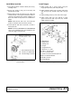
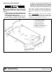
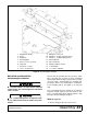
2. Place brace (2) inside the front corner of the weight
box (1) and secure with two cap screws (10), two
flat washers (12), and two lock nuts (14).
3. Align mounting plate (4) with slots of rear of weight
box. Secure with two cap screws (10), two flat
washers (12), and two lock nuts (14). Do not
tighten hardware at this point.
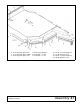
4. Align skid shoe (3) with holes on bottom and inside
of weight box. Secure bottom with the hardware
provided with skid shoe. Secure top with two cap
screws (10), two flat washers (12) and two lock
nuts (14).
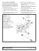
5. Place weight box assembly adjacent to the center
section and align hinge sections.
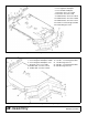
6. Insert hinge pin through the hinge sections. Install
sleeve (5) on hinge pin behind deck hinge section
to prevent weight box from sliding rearward.
Secure hinge pin with two washers (16) and two
spring pins (9).
7. Insert clevis pin (7) through lug on rear of weight
box and cylinder lug on center section with two
washers (16) as shown. Secure with cotter pin (8).
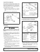
8. Insert self-tapping screw (11), lock washer (13),
and flat washer (12) through upper-rear hole in
mounting plate (4) and hole in side of center
section. Tighten hardware from step 3.
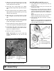
Winch Kit Installation (Optional)
Refer to page 81 for Installation and Operation instruc-
tions.