ROTARY CUTTER (Rev.
TO THE DEALER: Assembly and proper installation of this product is the responsibility of the Woods® dealer. Read manual instructions and safety rules. Make sure all items on the Dealer’s Pre-Delivery and Delivery Check Lists in the Operator’s Manual are completed before releasing equipment to the owner. The dealer must complete the online Product Registration form at the Woods Dealer Website which certifies that all Dealer Check List items have been completed.
TABLE OF CONTENTS INTRODUCTION . . . . . . . . . . . . . . . . . . . . . . . . . . . . . . . . . . . . . . . . . . . . . . 2 SPECIFICATIONS . . . . . . . . . . . . . . . . . . . . . . . . . . . . . . . . . . . . . . . . . . . . . 4 GENERAL INFORMATION . . . . . . . . . . . . . . . . . . . . . . . . . . . . . . . . . . . . . . 4 SAFETY VIDEO ORDER FORM . . . . . . . . . . . . . . . . . . . . . . . . . . . . . . . . . . 5 SAFETY RULES . . . . . . . . . . . . . . . . . . . . . . . . . . . . . . . . . . . . . .
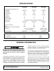
SPECIFICATIONS BW180HD BW180HDQ BW180HB BW180HBQ BW126HB BW180HBQ 1" - 15" 1" - 15" 1" - 15" Cutting Width 180" (15’) 180" (15’) 126" (10.
Safety Video Order Form BE SAFE! BE ALERT! BE ALIVE! BE TRAINED Before Operating Mowers! Safety Training Does Make a Difference. ASSOCIATION OF EQUIPMENT MANUFACTURERS Free Mower Safety Video Fill out and return the order form and we will send you a FREE VHS or DVD video outlining Industrial and Agricultural Mower Safety Practices.
Also, available from the Association of Equipment Manufacturers: A large variety of training materials (ideal for groups) are available for a nominal charge from AEM.
SAFETY RULES ATTENTION! BECOME ALERT! YOUR SAFETY IS INVOLVED! Safety is a primary concern in the design and manufacture of our products. Unfortunately, our efforts to provide safe equipment can be wiped out by an operator’s single careless act. In addition to the design and configuration of equipment, hazard control and accident prevention are dependent upon the awareness, concern, judgement, and proper training of personnel involved in the operation, transport, maintenance, and storage of equipment.
SAFETY RULES ATTENTION! BECOME ALERT! YOUR SAFETY IS INVOLVED! (Safety Rules continued from previous page) Make sure driveline guard tether chains are attached to the tractor and equipment as shown in the pamphlet that accompanies the driveline. Replace if damaged or broken. Check that driveline guards rotate freely on driveline before putting equipment into service. Before starting power unit, check all equipment driveline guards for damage. Replace any damaged guards.
SAFETY RULES ATTENTION! BECOME ALERT! YOUR SAFETY IS INVOLVED! Do not operate or transport equipment while under the influence of alcohol or drugs. Operate only in daylight or good artificial light. Keep hands, feet, hair, and clothing away from equipment while engine is running. Stay clear of all moving parts. Always comply with all state and local lighting and marking requirements. Never allow riders on power unit or attachment. Power unit must be equipped with ROPS or ROPS cab and seat belt.
SAFETY RULES ATTENTION! BECOME ALERT! YOUR SAFETY IS INVOLVED! (Safety Rules continued from previous page) Keep all persons away from operator control area while performing adjustments, service, or maintenance. Make certain all movement of equipment components has stopped before approaching for service. Frequently check blades. They should be sharp, free of nicks and cracks, and securely fastened. Do not handle blades with bare hands. Careless or improper handling may result in serious injury.
SAFETY & INSTRUCTIONAL DECALS ATTENTION! BECOME ALERT! YOUR SAFETY IS INVOLVED! Replace Immediately If Damaged! MODEL NO. SERIAL NO. Woods Equipment Company Oregon, Illinois, U.S.A. 1 - SERIAL NUMBER PLATE PN 1006348 - Located on Wheel Rims Use a clean, damp cloth to clean safety decals. Avoid spraying too close to decals when using a pressure washer; high-pressure water can enter through very small scratches or under edges of decals causing them to peel or come off.
SAFETY & INSTRUCTIONAL DECALS ATTENTION! BECOME ALERT! YOUR SAFETY IS INVOLVED! Replace Immediately If Damaged! 8 - PN 18864 WARNING DANGER DO NOT EXCEED PTO SPEED OF 1000 RPM PTO speeds higher than 1000 RPM can cause equipment failure and personal injury.
SAFETY & INSTRUCTIONAL DECALS ATTENTION! BECOME ALERT! YOUR SAFETY IS INVOLVED! Replace Immediately If Damaged! 12 - PN 1004991 WARNING TRANSPORT LOCK AND CYLINDER REQUIREMENTS RAISED CUTTER CAN DROP AND CRUSH SINGLE-ACTING FULL EXTENSION Cutte ers must be equipped with transport lock. 28-1/4" stands.
OPERATION The designed and tested safety of this machine depends on it being operated within the limitations as explained in this manual. Be familiar with and follow all safety rules in the manual, on the cutter and on the tractor. sturdy, rough-soled work shoes and protective equipment for eyes, hair, hands, hearing, and head; and respirator or filter mask where appropriate. The safe operation of this cutter is the responsibility of the operator, who must be properly trained.
3. Route the hose through the hose holder at the hitch and be sure the hose can slide freely in the holder. Do not allow hose slack to drag on the ground or become caught on tractor protrusions. 4. Attach the hydraulic hose to the tractor. 5. From the operator position, start tractor and raise and lower deck several times to purge trapped air from the hydraulic cylinder. Interference Check 1. Be sure that tractor 3-point lift links do not interfere with hydraulic hoses, cutter driveline, or cutter frame.
Be sure operator is familiar with all controls and can stop tractor and cutter quickly in an emergency. The operator should give complete, undivided attention to operating tractor and cutter. CUTTER OPERATION When beginning operation of the cutter, make sure that all persons are in a safe location. Power for operating the cutter is supplied by the tractor PTO. Operate PTO at 540 (1000 RPM for "Q" models). WARNING Do not operate or transport on steep slopes.
TRANSPORTING WARNING Power unit must be equipped with ROPS or ROPS cab and seat belt. Keep seat belt securely fastened. Falling off power unit can result in death from being run over or crushed. Keep foldable ROPS system in “locked up” position at all times. Always raise unit and install transport locks before transporting. Leak down or failure of mechanical or hydraulic system can cause equipment to drop. Always attach safety chain to tractor drawbar when transporting unit. Never exceed 20 mph (32.
STORAGE the PTO slip joint is lubricated and that the gearbox fluid levels are correct. Follow these steps when storing your cutter: 1. Clean cutter before storing. See page 23 for cleaning instructions. Store on level, solid ground. 2. Disconnect driveline and secure up off the ground. 3. Lower wings to ground. 4. Raise cutter center section and pin transport bar in raised position. 5. Attach parking jack and raise tongue weight off tractor drawbar. 6.
OWNER SERVICE The information in this section is written for operators who possess basic mechanical skills. If you need help, your dealer has trained service technicians available. For your protection, read and follow the safety information in this manual. WARNING Keep all persons away from operator control area while performing adjustments, service, or maintenance. Before working underneath, disconnect driveline from tractor, lower wings to ground, raise cutter, and pin transport bar in raised position.
1. 2. 3. 4. Driveline U-joint Telescoping shaft Carrier bearing block CV body assembly (10 pumps minimum) 5. Driveline shield 6. Splined yoke 10 Hours 10 Hours 40 Hours 10 hours 10 Hours 10 Hours 7. Gearbox (above lower line on dipstick) 8. Tongue pivot 9. Wheel yoke pivot 10. Tailwheel spindle 11. Turnbuckle 12. Tongue pivot Daily 40 Hours 40 Hours 20 Hours 40 Hours 40 Hours Figure 5.
Seasonal Lubrication lock clip (14), keyhole plate (13), and shims (11 & 12). Carefully drive blade pin (9) out of crossbar. In addition to the daily recommended lubrication, a more extensive application is recommended seasonally. 1. Fill CV double yokes with 20 pumps of grease with the joints in a straight line. 2. Articulate CV body to maximum angle several times to ensure full coverage of joints. 3. Place joints in the straight position and a add 10 additional pumps of grease to both joints. 4.
Blade Sharpening SLIP CLUTCH ADJUSTMENT (FIGURE 8) NOTICE ■ When sharpening blades, grind the same amount on each blade to maintain balance. Replace blades in pairs. Unbalanced blades will cause excessive vibration, which can damage gearbox bearings. Vibration may also cause structural cracks to cutter. 1. Sharpen both blades at the same time to maintain balance. Follow original sharpening pattern. 2. Do not sharpen blade to a razor edge—leave at least a 1/16" blunt edge. 3.
SHIELDING REPAIR DANGER Check wheels for low pressure, cuts, bubbles, damaged rims, or missing lug bolts and nuts. Never remove split rim assembly hardware (A) with the tire inflated. Full chain or rubber shielding must be installed when operating in populated areas or other areas where thrown objects could injure people or damage property. • If this machine is not equipped with full chain or rubber shielding, operation must be stopped when anyone comes within 300 feet (92 m).
TROUBLESHOOTING PROBLEM Does not cut POSSIBLE CAUSE SOLUTION Dull blades Sharpen blades. Worn or broken blades Replace blades. (Replace in pairs only.) Incorrect PTO speed Set at rated PTO speed. Ground speed too fast Reduce ground speed. Drive not functioning (blades do not turn when PTO is running) Check drive shaft connection. Check gearbox. Gearbox malfunction Repair gearbox. Excessive clutch slippage Adjust clutch.
DEALER SERVICE The information in this section is written for dealer service personnel. The repair described here requires special skills and tools. If your shop is not properly equipped or your mechanics are not properly trained in this type of repair, you may be time and money ahead to replace complete assemblies. WARNING Seal Replacement (Figure 12) Recommended sealant for gearbox repair is Permatex® Aviation 3D Form-A-Gasket or equivalent.
1. Disconnect and remove the rear driveline from the gearbox. 5. Remove six cap screws (23) and top cover (22) from housing. Remove gear (1) from inside housing. 2. Remove vent plug (24) and siphon gear lube from housing through this opening. 6. Remove oil seal (19) from front of housing (to be replaced). 3. Remove crossbar (see page 30). 7. Remove snap ring (10) and shim (13) from front of housing (2). Vertical Shaft Seal Replacement (Figure 13) 4.
correct diameter. Be sure not to damage the seal lip. 0.012". Check rotational torque by hand. The torque should be less than 2.2 lbs-inch. 8. Press in housing so that seal is recessed. Press protective seal (8) until seated flush with housing. Verify that the seal (8) is seated correctly. 16. Check that the gear backlash is between 0.006" and 0.016". You should not have to adjust the backlash. 9. Press bearing (7) into the housing, using a round tube of the correct diameter and a hand press.
SPLITTER GEARBOX REPAIR (Figure 14) 16. Inspect housing and caps for cracks or other damage. Removal from Cutter 1. Disconnect gearbox. and remove all drivelines from 2. Remove the four cap screw and lock nuts that secure gearbox to cutter, and remove gearbox. NOTE: Gearbox is heavy: do not attempt to move it without mechanical assistance. Disassembly Center Shaft 1. Remove plug from side of gearbox and pour out the gear oil. 2.
Check Gearbox 5. Install breather (12) in top cover. 1. Place top cover (10) on housing and secure into position using six cap screws (11). 2. Check gearbox for leaks by: plugging all holes except one, applying 4 psi of compressed air, and immersing gearbox in water. Verify gearbox does not leak. NOTE: Excessive air pressure will damage seals. Reinstallation on Cutter NOTE: Gearbox is heavy: do not attempt to move it without mechanical assistance. 1.
CROSSBAR REMOVAL 1. It is necessary to gain access to bottom side of cutter for crossbar removal. See Blocking Method page 19. NOTE: You will need to use either the puller screw (Item 6, Figure 16) or a small hydraulic jack to remove the crossbar. 2. Remove blades from crossbar as shown in Figure 15. 9. 10. 11. 12. 13. 14. 52. Blade pin Crossbar assembly Shim, 18 ga Shim, 20 ga Keyhole plate Blade lock clip 1/2 NC x 1-1/4 HHCS GR5 Figure 15. Blade Removal 3. Refer to Figure 16.
CROSSBAR INSTALLATION 1. Using emery cloth (220 or finer), remove surface rust, Loctite® and foreign material from hub, splined gearbox vertical shaft, and crossbar assembly. 2. Slide crossbar assembly (10) onto splined shaft. Install washer (71) and nut (72) and align a slot with hole in splined shaft. Torque nut to 800 lbs-ft. 3. Install cotter pin (73) through slot in nut and bend ends over. Figure 19 2.
4. Place universal cross in vise as shown in Figure 22 and tap on yoke to remove cup. Repeat Step 3 for final removal. Drive remaining cup out with a drift and hammer. SERVICING TIRES SAFELY Used Aircraft Tires (Figure 23) WARNING Do not attempt to mount a tire unless you have the proper equipment and experience to perform the job. Always maintain the correct tire pressure. Do not inflate tires above the recommended pressure. Never weld or heat a wheel and tire assembly.
ASSEMBLY INSTRUCTIONS DEALER SET-UP INSTRUCTIONS Assembly of this cutter is the responsibility of the WOODS dealer. It should be delivered to the owner completely assembled, lubricated and adjusted for normal cutting conditions. The BW180HB and BW126HB cutters are shipped completely assembled. The BW180HD cutter is shipped partially assembled. Assembly will be easier if components are aligned and loosely assembled before tightening hardware. Recommended torque values for hardware are located on page 72.
Install Height Adjustment Cylinder (BW180HD) Refer to Figure 25. 1. Attach base end of cylinder (5) to the spring arm (3) using clevis pin (18) and two cotter pins (66). 2. Extend cylinder rod and place transport lock bracket (7) over cylinder rod clevis. 3. Position cylinder rod and transport lock bracket between lugs on the wheel yoke tube and align holes. 4. Secure cylinder rod and transport lock bracket to the wheel yoke tube using clevis pin (20) and two cotter pins (66). 5.
Install Wheel and Hub (BW180HD) Install Tongue (BW180HD) 1. Insert wheel hub into outside of wheel yoke arm (1) and align holes. 1. Attach tongue (24) to center section using two tongue pivot pins (33) and cotter pins (70). 2. Secure into position using cap screw (54) and flanged lock nut (55). 2. Attach attitude rod (6) to lug on tongue and secure with clevis pin (34), washer (35), and cotter pin (66). 3. Attach wheel to hub using five lug nuts.
Install 3-Joint Drive - 540 RPM Only (BW180HD) Before installing cutter input driveline to gearbox, check the tag wired to the driveline and the tag wired to the input shaft of gearbox. Ensure the tag rpm speeds match the rpm speed decal on front of cutter. After confirming all speeds match, remove and discard tags and then complete driveline assembly. 1. Attach H-frame (26) to tongue with cap screw (45), sleeves (47), cup washers (46), and nut (48). 2. Coat splined end of gearbox input shaft with grease.
Install CV Drive (BW180HD)- Optional Before installing cutter input driveline to gearbox, check the tag wired to the driveline and the tag wired to the input shaft of gearbox. Ensure the tag rpm speeds match the rpm speed decal on front of cutter. After confirming all speeds match, remove and discard tags and then complete driveline assembly. 1. Align hole in drive yoke with groove on gearbox input shaft and slide rear half of drive (23) onto shaft. 2. Secure with bolt and nut supplied with drive. 7.
NOTE: Items 23 & 24 must be installed with square corners on top and facing cylinder as shown. 2. Slide spacer (17) and lock-up bar (19) over clevis pin (22) on back side of cylinder lug & secure with washer (27) and cotter pins (66). 3. Attach base end of wing cylinder (4) to cylinder links (23 & 24) using clevis pin (18) and cotter pins (66). 4. Remove plug from base end of hydraulic cylinder. Align cylinder rod end with cylinder lug on the wing and insert lock-up pin (26). 5.
Install Wing Wheel Yoke Adjustment Link (BW180HD) CAUTION Install Wing Driveline (BW180HD) 1. Attach clutch shield (16) to wing gearbox using four cap screws (60), lock washers (64), and flat washers (63). 2. Slide non clutch end of driveline (3) over wing gearbox shaft and align holes with groove. Use a suitable lifting device of sufficient capacity. Use adequate personnel to handle heavy components. 1. With a lifting device raise right wing and lock in the up position using the wing lock-up bar.
Install Chain or Belt Shielding (BW180HD) DANGER Full chain shielding must be installed when operating in populated areas or other areas where thrown objects could injure people or damage property. • If this machine is not equipped with full chain shielding, operation must be stopped when anyone comes within 300 feet (92 m). • This shielding is designed to reduce the risk of thrown objects.
4-Link 6-Link 5. Front wing chain plate, inner 6. Front wing chain plate, middle 7. Front wing chain plate, outer 8. Rear wing chain plate 16. 5/16 Chain - 6-link 18. 5/16 Chain - 4-link 19. 21. 22. 23. 1/2 NC x 1-1/2 Carriage bolt 1/2 NC Flange lock nut 3/8 NC x 1-1/4 Carriage bolt 3/8 NC Flange lock nut Figure 37.
1. 2. 3. 7. 8. 9. 12. 13. 22. 23. Front center belt shield plate Front right belt shield plate Front left belt shield plate Bent link, .25 x 1.72 x 13.00 Bent link, .25 x 9.25 x 9.50 Rubber shield, .25 x 8.75 x 40.76 Rubber shield, .25 x 9.25 x 28.00 Rubber shield, .25 x 9.25 x 18.25 3/8 NC x 1-1/4 Carriage bolt GR5 3/8 NC Flange lock nut Figure 38. Belt Shielding Installation - Center Section 4. 5. 6. 7. 10. 11.
DEALER CHECK LISTS PRE-DELIVERY CHECK LIST (DEALER’S RESPONSIBILITY) ___ Show customer how to determine the turning limits of the CV PTO driveline. Inspect the equipment thoroughly after assembly to ensure it is set up properly before delivering it to the customer. ___ Show customer the safe, proper procedures to be used when mounting, dismounting, and storing equipment. The following check lists are a reminder of points to inspect.
NOTES 44 Notes MAN0805 (4/30/2009)
PARTS INDEX BATWING® Rotary Cutter BW180HD, BW180HDQ BW180HB, BW180HBQ BW126HB, BW126HBQ MAIN FRAME ASSEMBLY (FRONT SECTION) .......................................................46-47 (BW180HD REAR SECTION) .......................................48-49 (BW180HB REAR SECTION)........................................50-51 WING ASSEMBLY ........................................................................................................52-53 GEARBOX ASSEMBLY WING & CENTER.................................
MAIN FRAME ASSEMBLY (FRONT SECTION) 74 - COMPLETE DECAL SET 75 - SAFETY DECAL SET 46 Parts Rev(10/23/2009) MAN0805 (4/30/2009)
MAIN FRAME ASSEMBLY (FRONT SECTION) REF PART QTY DESCRIPTION 1 19160KT 1 Blade kit, CCW 40 13759 3/4 NC x 2-1/4 HHCS GR5 2 ----- 1 Gearbox (see page 54) 41 28873 3/4 ID x 1-1/2 OD 1/4 Thick washer 3 1031174 1 Driveline complete, 2400, 1.75-20 3.4 42 13087 302207 REF 4 1031356 1 Tongue level bracket 43 5 1031362 1 2.56 x 3.00 x 2.
BW180HD - MAIN FRAME ASSEMBLY (REAR SECTION) 48 Parts MAN0805 (4/30/2009)
BW180HD - MAIN FRAME ASSEMBLY (REAR SECTION) DESCRIPTION REF PART QTY DESCRIPTION REF PART QTY 1 1027470 1 Center wheel yoke 21 ----- 2 57050 1 Access hole cover 29 14350 * 3/8 NC Flange lock nut 3 1027305 1 Spring arm 30 16148 5/16 NC x 3/4 Carriage bolt 14139 * 5/16 NC Flange lock nut 1 Tire & hub (see page 63) 4 19710 1 Compression spring 3.25 x .69 x 9.
BW180HB - MAIN FRAME ASSEMBLY (REAR SECTION) 50 Parts MAN0805 (4/30/2009)
BW180HB - MAIN FRAME ASSEMBLY (REAR SECTION) REF PART QTY DESCRIPTION 1 1031365 1 Center wheel yoke 30 16148 5/16 NC x 3/4 Carriage bolt 2 57050 1 Access hole cover 31 14139 * 5/16 NC Flange lock nut 3 1024109 2 Center spring wheel yoke arm 32 1003606 * 1 NC x 6 HHCS GR5 4 19710 2 Compression spring 3.25 x .69 x 9.
WING ASSEMBLY 52 Parts (Rev.
WING ASSEMBLY REF PART QTY DESCRIPTION 1 19160KT 1 Blade kit, CCW (Right wing) - or - 25 33647 1 Spacer, 3/4 1 19161KT 1 Blade kit, CW (Left wing) 26 32469 1 1 x 5 Lock-up pin REF PART QTY DESCRIPTION 2 ----- 1 Gearbox (see page 54) 27 11920 Washer, 1 x 1-7/8 x 1/4 3 1004934 1 Driveline complete 1340, 47.6 x 68.
WING & CENTER GEARBOX ASSEMBLY 54 Parts MAN0805 (4/30/2009)
WING & CENTER GEARBOX ASSEMBLY Center REF QTY 540 RPM 1000 RPM RIGHT WING A 1 58807 1031169 1031168 1 1 57445 1031164 57446 LEFT WING DESCRIPTION 58808 Complete gearbox 57446 Gear crown 2 1 ----- ----- ----- 3 1 57450 57450 57450 57450 Input shaft ----- Housing 4 1 57454 57454 57454 57454 Output shaft 5 1 57455 1031159 57447 57447 Gear pinion 6 1 39263 39263 39263 39263 Bearing cup & cone 7 2 39411 39411 39411 39411 Bearing cup & cone 8 1 57451 57451
SPLITTER GEARBOX ASSEMBLY REF PART QTY DESCRIPTION A 1031185 1 Complete splitter gearbox, 540 rpm A 1031186 1 Complete splitter gearbox, 1000 rpm 1 39411 6 Bearing 2 -------- 1 Housing 3 1031175 4 Oil seal, 45 mm x 85 mm x 10 mm 4 1002494 6 snap ring 85 dia 5 57471 6 Shim 6 1031176 2 Pinion gear, 540 rpm 6 1031178 2 Pinion gear, 1000 rpm 7 1031177 2 Shaft 1-3/4, 20 spline, wing 8 1031178 1 Gear, 540 rpm 8 1031176 1 Gear, 1000 rpm 9 1031179 1 Shaft 1-3/4, 20 spline, center 10
CENTER DECK DRIVE ASSEMBLY REF PART QTY 1 DESCRIPTION A 1031174 Complete center drive assembly 1 1031184 1 Yoke, 1-3/4, 20 spline 2 38352 2 Cross & bearing kit 3 1019108 1 Double yoke 4 1005521 1 5 1019114 6 1027217 7 57432 REF QTY DESCRIPTION 57440 1 Hub, 1-3/4, 20 spline 9 57434 1 Thrust plate 10 57439 1 Belleville spring plate 11 57259 6 M10 x 1.5P x 55 mm HHCS 8.8 Grease fitting 12 57260 6 M10 x 1.
FRONT DRIVE ASSEMBLY - EQUAL ANGLE REF PART QTY 1 DESCRIPTION Complete 540 rpm (6-spline) REF PART QTY DESCRIPTION A 57282 1 40563 1 Yoke 1-3/8, 6-spline (540 rpm) 11 40777 2 Anti-rotation chain 2 40566 2 Cross & bearing 12 40778 2 Screw (package of 10) 3 40751 2 Inboard yoke 13 18864 1 Danger decal, rotating driveline 4 40753 1 Outer profile 14 33347 1 Danger decal, shield missing 5 40765 2 Spring pin 10 x 90 15 19811 1 1/2 NC x 2 HHCS GR8 6 57299 1 Yok
REAR DRIVE ASSEMBLY - EQUAL ANGLE REF PART QTY DESCRIPTION REF PART QTY DESCRIPTION A 1004932 1 Complete rear drive assembly 10 40767 1 Support bearing 1 1004957 1 Yoke, 1-3/4, 20 spline 11 18864 1 Decal, danger rotating driveline 2 40566 1 Cross and bearing 12 33347 1 Decal, danger guard missing 3 1003471 1 Inboard yoke 13 1004960 1 Inner guard half 4 1004958 1 Inner profile 14 1004959 1 Outer guard half 5 40765 1 Spring pin 10 x 90 15 NSS 1 6 102993
TYPE A - 540 RPM & 1000 RPM FRONT CV DRIVE REF PART QTY DESCRIPTION REF PART QTY A A 1 2 2 3 4 5 1021103 1021104 19851 58774 58770 58759 58760 1021313 1 1 1 1 1 2 1 1 9 1021315 1 CV shield inner (540 RPM) 9 1021319 1 CV shield inner (1000 RPM) 1 Decal, danger guard missing (see page 13) 11 1021316 1 Yoke 55R x 36.4 x 1.69 - 20 (540 RPM) 11 1021320 1 Yoke 55R x 38.4 x 1.69 - 20 (1000 RPM) 5 1021317 1 12 58765 1 U-Joint cross and bearing kit 13 1023058 1 Yoke, 55R x 5.
TYPE B - 540 RPM & 1000 RPM FRONT CV DRIVE REF PART QTY DESCRIPTION REF PART QTY A A 1 2 2 3 4 5 1021103 1021104 19851 1033103 1033104 1033107 1033106 1033113 1 1 1 1 1 2 1 1 9 1021315 1 CV shield inner (540 RPM) 9 1021319 1 CV shield inner (1000 RPM) 1 Decal, danger guard missing (see page 13) 11 1021316 1 Yoke 55R x 36.4 x 1.69 - 20 (540 RPM) 11 1021320 1 Yoke 55R x 38.4 x 1.
WING DRIVE ASSEMBLY REF PART A 1004934 1 1004963 2 110 QTY DESCRIPTION REF PART QTY DESCRIPTION Complete wing drive assembly 16 1004965 4 Outer guard half 1 Yoke 1-3/4, 20 Spline 17 1004966 1 Inner guard half 2 Cross & bearing kit 18 1004951 1 Shaft assembly, male (complete w/guard) 19 1004934 1 Shaft assembly, female (complete w/guard) 20 57438 1 Flange yoke 21 57432 1 Friction disc (package of 2) 22 57440 1 Hub, 1-3/4, 20 Spline 23 57434 1 Thrust plate 2
5-BOLT WHEEL & TIRE ASSEMBLY REF PART QTY DESCRIPTION REF PART QTY DESCRIPTION 1 1017050 1 Heavy hub assembly (includes items 1 through 15) 16 1028820F 1 24 x 7.25 x 12 Aircraft tire, rim & hardware, foam filled - 5 bolt 2 1017034 1 Heavy wheel hub with cups (includes items 6,7,14) 16 1017030 1 29 x 9 x 15 Aircraft tire, rim & hardware - 5 bolt 3 1017033 1 Axle 17 1028821 1 4 1017027 1 Seal 12.
RUBBER SHIELDING - CENTER SECTION (FRONT & REAR) (STANDARD ON BW180 MODELS) REF PART QTY DESCRIPTION 1 1017057 1 Front center belt shield plate 2 1028588 1 Front right belt shield plate 3 1028589 1 Front left belt shield plate 7 1028506 2 Bent link .25 x 1.72 x 13.00 8 1028507 2 Bent link .25 x 1.72 x 9.50 9 1028592 2 Rubber shield .25 x 8.75 x 40.76 12 1027468 1 Rubber shield .25 x 9.25 x 28.00 13 1027469 2 Rubber shield .25 x 9.25 x 18.
RUBBER SHIELDING - WING (FRONT & REAR) (STANDARD ON BW180 MODELS) REF PART QTY DESCRIPTION 4 1028590 1 Front right wing belt shield plate, inside -or- 4 1028591 1 Front left wing belt shield plate, inside 5 1027496 1 Front right wing belt shield plate, middle -or- 5 1027497 1 Front left wing belt shield plate, middle 6 1028504 1 Front right wing belt shield plate, outer -or- 6 1028505 1 Front left wing belt shield plate, outer 7 1028506 4 Bent link .25 x 1.72 x 13.
CHAIN SHIELDING - CENTER SECTION (FRONT & REAR) (SINGLE ROW OPTIONAL ON BW180 MODELS) (SINGLE ROW STANDARD ON BW126 MODELS) (DOUBLE ROW OPTIONAL ON BW126 & BW180 MODELS) SINGLE ROW REF PART QTY 1 1017124 1 2 1028596 1 3 1028597 4 1027460 5 1027461 9 DOUBLE ROW DESCRIPTION REF PART QTY Front center chain plate 1 1017124 1 Front center chain plate Front right chain plate 2 1028596 1 Front right chain plate 1 Front left chain plate 3 1028597 1 Front left chain plate 1 Rear
CHAIN SHIELDING - WING (FRONT & REAR) (SINGLE ROW OPTIONAL ON BW180 MODELS) (SINGLE ROW STANDARD ON BW126 MODELS) (DOUBLE ROW OPTIONAL ON BW126 & BW180 MODELS) SINGLE ROW REF PART DOUBLE ROW QTY DESCRIPTION REF PART QTY DESCRIPTION 5 1028598 1 Front right wing chain plate, inner -or 5 1028598 1 Front right wing chain plate, inner -or 5 1028599 1 Front left wing chain plate, inner 5 1028599 1 Front left wing chain plate, inner 6 1028500 1 Front right wing chain plate, middle -or
HYDRAULIC CYLINDERS REF 2 Wing 3 x 10 Center 3.
HYDRAULIC CYLINDER STROKE CONTROL KIT REF PART QTY DESCRIPTION 1 24098 1 Stroke control set for 1-1/4" cylinder rod (contains items 2 - 5) 2 –––– 2 1-1/2" Segment 3 –––– 1 1-1/4" Segment 4 –––– 1 1" Segment 5 –––– 1 3/4" Segment CROSSBAR PULLER (OPTIONAL) REF PART QTY DESCRIPTION REF PART QTY DESCRIPTION A 8811 1 Crossbar puller, complete 4 24879 1 Crossbar puller pad assembly 1 19914 2 Crossbar puller clevis 5 24876 1 Crossbar puller tube assembly 2 3097 *
BW126HB / BW126HBQ WEIGHT BOX ASSEMBLY (OPTIONAL) REF PART QTY DESCRIPTION 1 1027345 1 Weight box 750 lbs 29 14350 * 2 1028584 1 Brace 30 565 * 3/8 Flat washer 3 1010985 1 Skid shoe 31 838 * 3/8 Lock washer 4 1028566 1 Mounting plate 32 19446 * 6 1003559 1 1.25 x 1.500 x 3.40 Sleeve 34 46605 15 1003495 1 Hinge pin 35 1863 * REF PART QTY DESCRIPTION 3/8 NC x Flange lock nut 3/8 NC x 1-1/4 Self-tapping screw 1 Clevis pin, 1 x 2.
WINCH KIT (OPTIONAL) REF PART QTY DESCRIPTION A 1019456 - Winch kit, complete 1 52478 4 Idler bracket 2 6696 2 Chain idler casting 3 409 2 Clevis pin, 1/2 x 2 4 22411 2 Klik pin, 3/16 x 1 5 3379 * - HHCS, 1/2 NC x 1-1/2 GR5 6 11900 * - Lock nut, 1/2 NC flanged 7 1863 * - Washer, 1" SAE flat 2 Headless pin, 1 x 4 drilled 8 9 1008325 1266 * Winch Kit Installation 1. Locate and drill one 9/16" hole in each wing as shown.
BOLT TORQUE CHART Always tighten hardware to these values unless a different torque value or tightening procedure is listed for a specific application. Fasteners must always be replaced with the same grade as specified in the manual parts list. Always use the proper tool for tightening hardware: SAE for SAE hardware and Metric for metric hardware. Make sure fastener threads are clean and you start thread engagement properly.
BOLT SIZE CHART NOTE: Chart shows bolt thread sizes and corresponding head (wrench) sizes for standard SAE and metric bolts. SAE Bolt Thread Sizes 5/16 3/8 1/2 IN MM 5/8 3/4 7/8 1 2 3 4 5 6 7 25 50 75 100 125 150 175 Metric Bolt Thread Sizes 8MM 10MM 12MM 14MM 16MM 18MM ABBREVIATIONS AG .............................................................. Agriculture ASABE.................... American Society of Agricultural & Biological Engineers (formerly ASAE) ASAE .......
INDEX A O ADJUSTMENTS Cutting Height Slip Clutch 22 OPERATION 15 Connecting Cutter to Tractor ASSEMBLY Dealer Set-Up Instructions Fill Gearboxes 33 14 Cutting Height Adjustment 15 CV Driveline Turning Limits 15 Hydraulic Connection 14 Interference Check 15 33 Cutter Operation 16 Mowing Tips 16 Shredding 16 D Pre-Operation Check List (Owner’s Responsibility) 18 DEALER CHECK LIST Storage 18 Tractor Operation Transporting 17 Check Lists Delivery (Dealer’s Responsibility) 43 Pre-Delivery (Deal
WARRANTY All Models Except Mow’n MachineTM Zero-Turn Mowers Please Enter Information Below and Save for Future Reference. Date Purchased: ____________________________ From (Dealer): __________________________________________ Model Number: ____________________________ Serial Number: __________________________________________ Woods Equipment Company (“WOODS”) warrants this product to be free from defect in material and workmanship.
WARRANTY (Replacement Parts For All Models Except Mow’n MachineTM Zero-Turn Mowers and Woods BoundaryTM Utility Vehicles) Woods Equipment Company (“WOODS”) warrants this product to be free from defect in material and workmanship for a period of ninety (90) days from the date of delivery of the product to the original purchaser with the exception of V-belts, which will be free of defect in material and workmanship for a period of 12 months.