59757 Sub-Frame Mounting Kit Woods Backhoe Model mounting to BH6500 Ford/New Holland Tractor Models TC18, TC21 Compatible with: New Holland Loader 7106 or Woods Loader 1006 MANUAL PART NUMBER 59756 PN-59756 (Rev.
TO THE DEALER: Assembly and proper installation of this product is the responsibility of the WOODS dealer. Read manual instructions and safety rules. Make sure all items on the Dealer’s Pre-Delivery and Delivery Check Lists in the Operator’s Manual are completed before releasing equipment to the owner. The dealer must complete the Warranty Registration included in this manual. Both dealer and customer must sign the registration which certifies that all Dealer Check List items have been completed.
TABLE OF CONTENTS INTRODUCTION . . . . . . . . . . . . . . . . . . . . . . . . . . . . . . . . . . . . . . . . . . . . . . .ii SAFETY RULES . . . . . . . . . . . . . . . . . . . . . . . . . . . . . . . . . . . . . . . . . . . . . . 3 INSTALLATION INSTRUCTIONS . . . . . . . . . . . . . . . . . . . . . . . . . . . . . . . . . 4 PUMP KIT INSTALLATION . . . . . . . . . . . . . . . . . . . . . . . . . . . . . . . . . . . . . 12 #59757 SUB-FRAME MOUNTING KIT . . . . . . . . . . . . . . . . . . . . . . . . . . . .
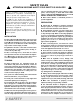
SAFETY RULES ATTENTION! BECOME ALERT! YOUR SAFETY IS INVOLVED! Safety is a primary concern in the design and manufacture of our products. Unfortunately, our efforts to provide safe equipment can be wiped out by an operator’s single careless act. In addition to the design and configuration of equipment, hazard control and accident prevention are dependent upon the awareness, concern, judgement, and proper training of personnel involved in the operation, transport, maintenance and storage of equipment.
SAFETY RULES ATTENTION! BECOME ALERT! YOUR SAFETY IS INVOLVED! check and comply with these instructions may result in serious injury or death. n Remove seat and upper support assembly before installing or removing backhoe from tractor. Failure to comply may result in equipment failure and/or personal injury. n If tractor is equipped with draft sensing control, set control to “HEAVY” (minimum sensitivity) position.
BACKHOE SUB-FRAME INSTALLATION Safety is a primary concern in the design and manufacture of our products. Unfortunately, our efforts to provide safe equipment can be wiped out by an operator’s single careless act. In addition to the design and configuration of equipment, hazard control and accident prevention are dependent upon the awareness, concern, judgement, and proper training of personnel involved in the operation, transport, maintenance and storage of equipment.
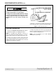
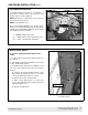
SUB-FRAME INSTALLATION Cont’d CAUTION n If you do not understand any part of this manual and need assistance, see your dealer. n Always wear relatively tight and belted clothing to avoid entanglement in moving parts. Wear sturdy, rough-soled work shoes and protective equipment for eyes, hair, hands, hearing, and head. * Operator’s seat must be located in the lowest and most forward position to obtain 40” minimum radius. Figure 1 Sub-Frame Clearance TRACTOR PREPARATION 1.
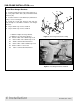
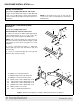
SUB-FRAME INSTALLATION Cont’d Install Rear Hanger Brackets 1. Install new right and left rear hanger brackets (1, 2), using eight 10mm bolts (20) and hardened flat washers (22). 2. Install six 10mm x 1.5P x 80mm (21) and washers (22) to secure rear hangers. 3. Install cap screws (25), washers (29), and nuts (28) through crossmembers welded to rear hanger brackets. 22 2 21 20 1 22 28 29 4. Torque 10mm cap screws to 29 lbs-ft. 5. Torque 12mm cap screws to 50 lbs-ft. 29 25 1.
SUB-FRAME INSTALLATION Cont’d Install Mid-mount Bracket GREASE FITTINGS 1. Install mid-mount bracket (3) to underside of transmission housing, using cap screws (23) and washers (29) as shown in Figure 4. NOTE: Bracket has a small notch, to be positioned on the left side the the tractor. NOTE: Leave hardware loose. 2. The mounting kit will limit access for two grease fittings on the clutch and brake pedals.
SUB-FRAME INSTALLATION Cont’d Modify Loader Mounts For tractors equipped with Woods 1006 Loader Loader mounts manufactured prior to April 2001 will need to be modified before reinforcement brackets can be installed. Contact Woods Technical Service for assistance. NOTE: If rear mount has five slots on each side, proceed to next section, Install Right & Left Reinforcement Brackets.
SUB-FRAME INSTALLATION Cont’d Install Crossmember 1. Attach crossmember bracket (4) to right and left reinforcement brackets, using cap screws (24) and washers (29) as shown in Figure 9. 4. 1000581 Crossmember bracket 24. 307301 M12–1.75P x 40mm Cap screw 29. 57811 1/2 Hardened flat washer, extra thick 24 29 4 Figure 9 Crossmember Bracket Installation PN-59756 (Rev.
SUB-FRAME INSTALLATION Cont’d Sub-Frame Fit-Up 1. Insert sub-frame (1) into rear mounting bracket cradle (2 & 3). 2. Secure with clevis pins (17) and safety pins (19). 3. Pivot sub-frame up and secure to front mount (6) with bent pin (7) and Klik pin (18). 4. Remove sub-frame from tractor. 5. Tighten 12mm hardware to 50 lbs.-ft. IMPORTANT ■ DO NOT install the 3-point hitch top link on this subframe mounting kit. No top link bracket should be used on this backhoe. 6 19 18 17 7 17 19 1 2 3 CD4891 1. 2.
SUB-FRAME INSTALLATION Cont’d Attaching Sub-Frame to Backhoe 1. With sub-frame removed from tractor, attach to the backhoe using four cap screws (13), six lock washers (14), and six nuts (15). 2. Align step (12) and insert two cap screws (7) through sub-frame holes. Secure with lock washers (6) and nuts (5). 5. 6. 7. 12. 13. 14. 15.
SUB-FRAME INSTALLATION Cont’d Mount Bracket to Pump Kit NOTE: For complete information on pump kit installation, consult the Woods BH6500/7500 backhoe operators manual #37541. The pump mounting bracket is designed to slip over the tractor drawbar and prevent the pump from rotating. 1. Trim the bracket flush with the bottom of the tractor drawbar if necessary. 2. Attach pump mounting bracket #59760 (2) to pump assembly as shown in Figure 12. 3. Secure with cap screw (5) and lock nut (3) as shown. 4.
SUB-FRAME & BACKHOE TO TRACTOR Mount Sub-Frame & Backhoe to Tractor DANGER n The sub-frame mount is designed to provide secure mounting and adequate operator clearance when properly installed. Check clearance dimensions shown in figure 1 to be sure you have installed sub-frame correctly. Follow all mounting instructions in this manual. Do not operate backhoe unless there is adequate clearance. Failure to check and comply with these instructions may result in serious injury or death.
SUB-FRAME & BACKHOE TO TRACTOR Cont’d Connect Hydraulic System WARNING n Keep hands and body away from pressurized lines. Use paper or cardboard, not hands or other body parts to check for leaks. Wear safety goggles. Hydraulic fluid under pressure can easily penetrate skin and will cause serious injury or death.
SUB-FRAME & BACKHOE to TRACTOR Cont’d Remove Backhoe With Sub-Frame DANGER n The only time the backhoe may be operated from a position other than the operator seat is during backhoe attachment and removal. Operator must • Read Sub-Frame Mounting Kit Manual instructions on attaching and removing backhoe and use extreme care • Always stand between rear tire and backhoe stabilizer arms or along side of tractor to avoid being trapped should the boom swing control be accidentally activated. 1.
#59757 SUB-FRAME MOUNTING KIT 30 15 21 22 20 1 2 22 25 29 28 6 29 29 24 28 29 3 29 25 5 28 29 29 27 29 26 32 10 28 29 29 25 23 33 29 24 29 4 31 7 36 35 8 34 9 16 CD5888 Serial Number Plate Located inside sub-frame side rail, rear of cross tube MODEL NO. SERIAL NO. ID NO. MASS (KG) YR OF MFG. OREGON, IL U.S.A. 16 Parts PN-59756 (Rev.
#59757 SUB-FRAME MOUNTING KIT PARTS LIST REF PART QTY DESCRIPTION REF PART QTY DESCRIPTION 1 1000578 1 BRACKET-REAR HANGER RT 23 62584 4 HHCS M12-1.75P X 35MM 2 1000579 1 BRACKET-REAR HANGER LT 24 307301 6 HHCS M12-1.75P X 40MM 3 1000590 1 BRACKET-MID MOUNT 25 58515 8 HHCS M12-1.75P X 45MM CL10.9ZP 4 1000581 1 BRACKET-CROSS MEMBER 26 58516 2 HHCS M12-1.75P X 50MM CL10.9ZP 5 1000594 1 BRACKET-REINFORCEMENT RT 27 307302 4 HHCS M12-1.
BOLT TORQUE CHART Always tighten hardware to these values unless a different torque value or tightening procedure is listed for a specific application. Fasteners must always be replaced with the same grade as specified in the manual parts list. Always use the proper tool for tightening hardware: SAE for SAE hardware and Metric for metric hardware. Make sure fastener threads are clean and you start thread engagement properly.
BOLT SIZE CHART NOTE: Chart shows bolt thread sizes and corresponding head (wrench) sizes for standard SAE and metric bolts. SAE Bolt Thread Sizes 5/16 IN MM 3/8 1/2 5/8 3/4 7/8 1 2 3 4 5 6 7 25 50 75 100 125 150 175 Metric Bolt Thread Sizes 8MM 10MM 12MM 14MM 16MM 18MM ABBREVIATIONS AG............................................................. Agriculture NC ....................................................National Coarse ATF ..............................
WARRANTY (Replacement Parts For All Models Except Mow’n Machines) WEC Company, d/b/a Woods Equipment Company (“WOODS”), warrants this product to be free from defect in material and workmanship for a period of ninety (90) days from the date of delivery of the product to the original purchaser. Under no circumstances will this Warranty apply in the event that the product, in the good faith opinion of WOODS, has been subjected to improper operation, improper maintenance, misuse, or an accident.
WARRANTY (All Models Except Mow’n Machines) Please Enter Information Below and Save For Future Reference. Date Purchased: __________________________ From (Dealer): _____________________________ Model Number: __________________________ Serial Number: _____________________________ WEC Company, d/b/a Woods Equipment Company (“WOODS”), warrants this product to be free from defect in material and workmanship.
PART NO. 59756 Woods Equipment Company 2606 Illinois Route 2 South Post Office Box 1000 Oregon, Illinois 61061 815-732-2141 tel 815-732-7580 fax © 1999 Woods Equipment Company. All rights reserved.