INSTALLATION INSTRUCTIONS AND REPAIR PARTS INFORMATION #111307 LOADER MOUNTING KIT for mounting DuAl Model 195 Loader to John Deere 5500 2WD Tractors #118460 LOADER MOUNTING KIT for mounting DuAl Model 215 Loader to John Deere 5500 FWA Tractors #199758 HYDRAULIC HOSE KIT for mounting DuAl Model 195 & 215 Loaders to John Deere 5500 Tractors PN-53661 (Rev.
TO THE DEALER: The loader mounting kit and/or hydraulic hose kit assembly and proper installation to the tractor is the responsibility of the DuAl dealer. Read manual instructions and safety rules. Make sure all items on the Pre-Delivery and Delivery Check Lists in the loader manual are completed before releasing equipment to the owner. TO THE OWNER: Read these mounting instructions before installing loader mounting kit and/or hydraulic hose kit.
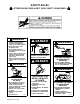
SAFETY RULES ATTENTION! BECOME ALERT! YOUR SAFETY IS INVOLVED! WARNING D Read and understand Operator’s Manual before operating (available from dealer or call 1-800-319-6637). D Keep others away when operating loader. D Do not allow children or untrained persons to operate equipment. D Lower loader to ground, stop engine, set park brake and remove key before leaving tractor seat. D Failure to follow safety rules can result in serious injury or death.
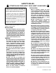
SAFETY RULES ATTENTION! BECOME ALERT! YOUR SAFETY IS INVOLVED! PREPARATION Safety is a primary concern in the design and manufacture of our products. Unfortunately, our efforts to provide safe equipment can be wiped out by a single careless act of an operator. J Air in hydraulic systems can cause erratic operation and allows loads or equipment components to drop unexpectedly.
SAFETY RULES ATTENTION! BECOME ALERT! YOUR SAFETY IS INVOLVED! and all raised components to the ground, operate valve levers to release any hydraulic pressure, stop engine, set parking brake, remove key, and unfasten seat belt. (Safety Rules continued from previous page) J Ensure shields and guards are properly installed and in good condition. Replace if damaged.
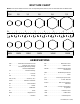
BOLT SIZE CHART NOTE: Chart shows bolt thread sizes and corresponding head (wrench) sizes for standard SAE and Metric Bolts. SAE Bolt Thread Sizes 5/16 IN MM 3/8 1/2 5/8 3/4 7/8 1 2 3 4 5 6 7 25 50 75 100 125 150 175 Metric Bolt Thread Sizes 8MM 10MM 12MM 14MM 16MM 18MM ABBREVIATIONS ATF . . . . . . . . . Automatic Transmission Fluid NC . . . . . . . . . . . . . . . . . . . . . National Coarse CE . . . . . . . . . . . . . . . .
BOLT TORQUE CHART After every ten (10) hours of operation, check all hardware and tighten where required. SAE Series Torque Chart DO NOT use these values if a different torque value or tightening procedure is listed for a specific application. Torque values listed are for general use only. Fasteners should be replaced with the same grade. Make sure fastener threads are clean and you properly start thread engagement. This will prevent them from failing when tightening.
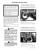
MOUNTING INSTRUCTIONS Front Mount Attachment -- 195 Loader Safety is a primary concern in the design and manufacture of our products. Unfortunately, our efforts to provide safe equipment can be wiped out by a single careless act of an operator. Attach the front mount (1) to the front of the tractor bolster and secure with four cap screws (16) and lockwashers (15). Tighten all fasteners securely.
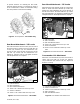
Rear Mount Attachment -- 215 Loader To provide clearance for mounting the 215 loader, adjust the front tractor tires to a minimum 67”tread or to the manufacturer’s widest recommended setting. This also provides increased tractor stability. Attach the front of the left rear mount (3) to the tractor frame as shown and secure with two cap screws (14), washers (13) and lockwashers (12). Secure the rear of the left rear mount to the tractor with four cap screws (18) and lockwashers (17).
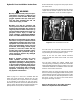
Hydraulic Hose Installation Instructions Refer to illustration on page 10 for the proper orientation of the hoses. Connect the end of the hose with the quick disconnect coupler into the female couplers on the rear of the tractor to complete the circuit, as shown in Figure 7. WARNING J Keep hands and body away from pressurized lines. Use paper or cardboard, not body parts to check for leaks. Wear safety goggles.
#111307 LOADER MOUNTING KIT 18 17 11 2 4 13 12 10 3 1 CD4941 13 15 16 Ref Part No No 1 53631 2 53306-1 3 53307-1 4 53264 No Used 1 1 1 1 Description Front mount Right rear mount Left rear mount .50 x 6.00 x 18.87 U-Link Part No 12 1286 * 5/8 Lockwasher, plated 13 692 * 5/8 Flat washer plated 15 Ref No 10 11 Part No 43104 * 65541 Description 14mm x 1.5P Hex nut 14mm x 1.5P x 50mm Hex head cap screw PN-53661 (Rev. 12/96) 14 Ref No 14 HARDWARE 12 23446 2522 * 16mm x 2.
#118460 LOADER MOUNTING KIT 18 17 11 2 4 13 12 10 3 CD4942 5 13 12 19 12 14 6 Ref No 2 3 4 5 6 Ref No 10 11 Part No 53808 53809 53264 53820 53821 Part No 43104 * 65541 No Used 1 1 1 1 1 Description Right rear mount Left rear mount .50 x 6.00 x 18.87 U-Link Right front mount Left front mount HARDWARE Description 14mm x 1.5P Hex nut 14mm x 1.
#199758 HYDRAULIC HOSE KIT 215 LOADER D 195 LOADER B A D C C B A 2 3 D CD4943 C B A 1 Ref No Part No No Used 1 53670 4 Hose -- 3/8, 150”, 3/4 JICM x 3/4 JICM with vinyl protector 2 31-3053 4 90°Swivel elbow 3 66511 4 Quick coupler -- male Description Part No 39-5063 39-5062 39-5061 89 Items Not Shown No Used 2 2 2 4 Description Plastic spiral band -- orange Plastic spiral band -- blue Plastic spiral band -- red Plastic tie LOADER VALVE FUNCTION CHART HANDLE FORWARD BOOM DO
NOTES 12 PN-53661 (Rev.
WARRANTY Please enter information below and SAVE FOR FUTURE REFERENCE. Date Purchased: From (Dealer): Model Number: Serial Number: WOODS warrants each new WOODS product to be free from defects in material and workmanship. This warranty is applicable only for the normal service life expectancy of the machine or components, not to exceed twelve consecutive months from the date of delivery of the new WOODS product to the original purchaser.
PART NUMBER 53661 Woods Equipment Company 2606 Illinois Route 2 South Post Office Box 1000 Oregon, Illinois 61061 815-732-2141 tel 815-732-7580 fax LITHO IN USA