MODEL W1736 OVERARM ROUTER INSTRUCTION MANUAL Phone: 1-360-734-3482 • On-Line Technical Support: tech-support@shopfox.biz COPYRIGHT © OCTOBER, 2004 BY WOODSTOCK INTERNATIONAL, INC. #6617TR WARNING: NO PORTION OF THIS MANUAL MAY BE REPRODUCED IN ANY SHAPE OR FORM WITHOUT THE WRITTEN APPROVAL OF WOODSTOCK INTERNATIONAL, INC.
WARNING Some dust created by power sanding, sawing, grinding, drilling, and other construction activities contains chemicals known to the State of California to cause cancer, birth defects or other reproductive harm. Some examples of these chemicals are: • Lead from lead-based paints. • Crystalline silica from bricks, cement, and other masonry products. • Arsenic and chromium from chemically treated lumber. Your risk from these exposures varies, depending on how often you do this type of work.
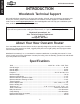
SAFETY SET UP OPERATIONS MAINTENANCE INTRODUCTION ..................................................................................................2 Woodstock Technical Support ............................................................................ 2 About Your New Overarm Router ........................................................................ 2 Specifications ............................................................................................... 2 Controls and Features ..............
INTRODUCTION W1736 Overarm Router INTRODUCTION Woodstock Technical Support We stand behind our machines! In the event that a defect is found, parts are missing or questions arise about your machine, please contact Woodstock International Technical Support at 1-360-734-3482 or send e-mail to: tech-support@shopfox.biz. Our knowledgeable staff will help you troubleshoot problems, send out parts or arrange warranty returns. If you need the latest edition of this manual, you can download it from http://www.
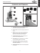
INTRODUCTION W1736 Overarm Router Controls and Features A B F C D G E A. Top Valve: Controls the speed that the router rises from the plunge (down) position. B. Bottom Valve: Controls the plunge speed of the router. C. Head: The part of the overarm assembly that houses the router motor and moves up and down when activated by the foot pedal. D. Pin Adjustment Knob: Locks the table pin in place for pin routing operations. E.
W1736 Overarm Router SAFETY SAFETY READ MANUAL BEFORE OPERATING MACHINE. FAILURE TO FOLLOW INSTRUCTIONS BELOW WILL RESULT IN PERSONAL INJURY. Indicates an imminently hazardous situation which, if not avoided, WILL result in death or serious injury. Indicates a potentially hazardous situation which, if not avoided, COULD result in death or serious injury. Indicates a potentially hazardous situation which, if not avoided, MAY result in minor or moderate injury.
W1736 Overarm Router 12. Do not force tool. The machine will do a safer and better job at the rate for which it was designed. 13. Use correct tool. Do not force machine or attachment to do a job for which it was not designed. 15. Remove adjusting keys, rags, and tools. Before turning the machine on, make it a habit to check that all adjusting keys and wrenches have been removed. 16. Avoid using an extension cord. But if you must use one, examine the extension cord to ensure it is in good condition.
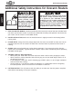
W1736 Overarm Router Additional Safety Instructions for Overarm Routers SAFETY READ and understand this entire instruction manual before using this machine. Serious personal injury may occur if safety and operational information is not understood and followed. DO NOT risk your safety by not reading! USE this and other machinery with caution and respect. Always consider safety first, as it applies to your individual working conditions.
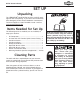
W1736 Overarm Router SET UP Unpacking The SHOP FOX® Model W1736 has been carefully packaged for safe transporting. If you notice the machine has been damaged, please contact Woodstock International Technical Support at 1-360-734-3482 or send e-mail to: tech-support@shopfox.biz Items Needed for Set Up • • • • • • • • • Air Compressor .............................................1 Air Hose with 3/8" Female Quick Connect Fitting ...1 Hex Wrench 6mm..........................................1 Hex Wrench 8mm..
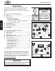
W1736 Overarm Router Inventory SET UP The following is a description of the inventory of the components shipped with the SHOP FOX® Model W1736. Lay the components out and inventory your shipment. SUFFOCATION HAZARD! Immediately discard all plastic bags and packing materials to eliminate choking/suffocation hazards for children and animals. Main Inventory Components (Figure 1) A. Table ........................................................1 B. Support Arm ..............................................
W1736 Overarm Router Assembling Overarm Router 1. Using four M10-1.5 x 45 cap screws and lock washers, attach the support arm to the table with the rubber gasket in the middle (see Figure 3). 2. Mount the head assembly to the support arm with four M10-1.5 x 25 cap screws and lock washers (see Figure 3), and tighten evenly. 3. Attach the side guard to the head assembly with two flat head screws (see Figure 3). 5. 6.
W1736 Overarm Router Mounting For stable and safe operation, the overarm router should be mounted to a workbench. If you intend on using the overarm router for portable applications, mount it to a heavy plywood base (at least 1" thick) that is wide enough to prevent tipping or rocking. Clamp the base to the workbench or stable work surface before operating the router. ����� To mount the overarm router, do these steps: SET UP 1.
W1736 Overarm Router Attaching Foot Switch The foot switch attaches to the valves on the overarm router assembly with the two small air hoses. The air hose ports at the foot switch are labeled "R" and "S", as shown in Figure 7. To attach the foot switch, do these steps: Attach the hose connected to port "R" to the top valve (see Figure 8) on the air cylinder by pushing the hose into the fitting. 2.
W1736 Overarm Router Installing Router The adapters included with the Model W1736 are designed for most common sizes of Makita, Milwaukee, Bosch, Porter-Cable, and Dewalt routers that have detachable bases. SET UP To install a router motor into the overarm router assembly, do these steps: 1. Remove your router motor from its base and measure the diameter of the router motor or the base from which it was removed.
W1736 Overarm Router Aligning Router with Table Pin The router motor must be aligned with the table pin to ensure accurate work during pin routing operations. ������������ ��������������������� To check/align the router to the table pin, do these steps: Install a 1/4" straight bit into the router. 2. Insert the 1/4" table pin into the center of the table so the 1/4" side of the pin is facing up. 3.
W1736 Overarm Router Connecting to Air Depending on the type of air fitting you have on the end of your air hose, you may need to replace the included male 1/4 NPT fitting with the style of 1/4 NPT fitting suitable for the female quick connect in your shop. To connect your overarm router to the air compressor, do these steps: SET UP 1. 2. Regulate the pressure of your air compressor to 60 PSI.
W1736 Overarm Router OPERATIONS General We strongly recommend that you read books, trade articles or seek training with overarm routers before performing any cuts in which you are not confident. Above all, your safety should come first. This recommended research will pay off with your increased safety, the quality of your work and the gain in knowledge you will make as a woodworker.
W1736 Overarm Router Adjusting Plunge Depth The height adjustment nuts, shown in Figure 16, limit how far down the router will plunge when the foot switch is pressed. OPERATIONS To adjust the height, do these steps: 1. Move the router guard all the way up and temporarily tighten it in place. 2. Loosen the top adjustment nut. 3. Turn both nuts up or down, as needed, and test the plunge depth by pressing the foot pedal. Repeat this step until the plunge depth is at the correct height. 4.
W1736 Overarm Router Using Table Pins The table pins are provided so you can use your router as a "Pin Router" (see Figure 17). Three double-sided table pins are included with your overarm router in the following sizes: 3/16", 1/4", 5/16", 3/8", 7/16", and 1/2". Pin Location With a table pin installed, the operator can use a prerouted pattern jig to easily replicate a pattern onto a workpiece that is clamped to the jig. See Figure 18 for details. To use a table pin, do these steps: 1.
W1736 Overarm Router MAINTENANCE General Regular periodic maintenance on your SHOP FOX® Model W1736 will ensure its optimum performance. Make a habit of inspecting your table saw each time you use it.
W1736 Overarm Router Troubleshooting This section covers the most common overarm router problems. DO NOT make any adjustments until the overarm router is unplugged, disconnected from air, and has completely stopped moving. If you need additional help, please contact Woodstock International Technical Support at 1-360-734-3482 or send email to: tech-support@shopfox.biz. SYMPTOM POSSIBLE CAUSE CORRECTIVE ACTION Router will not plunge when foot switch is pressed. 1.
W1736 Overarm Router PARTS ���� ���� ���� ���� ���� ���� ���� ���� � � � �� �� � ���� ���� ���� �� � �� �� �� �� � �� �� � � ���� ���� ���� �� �� �� �� �� �� �� ���� �� �� �� �� �� �� �� �� �� �� �� �� ��� �� �� �� �� �� PARTS �� �� �� ��� �� �� �� �� ��� ��� �� �� -20-
W1736 Overarm Router REF PART # 1 2 3 4 5 6 8 9 10 11 12 13 14 15 16 17 18 18-1 18-3 18-4 18-5 18-6 18-7 19 20 21 22 23 24 25A 25B 25C 26 27 XPSB70M XPLW06M X1736003 X1736004 X1736005 XPS02M X1736008 XPSB64M XPLW06M XPLN05M X1736012 X1736013 X1736014 X1736015 XPFH07M XPRP07M X1736018 X1736018-1 X1736018-3 X1736018-4 X1736018-5 X1736018-6 X1736018-7 X1736019 X1736020 X1736021 XPR54M X1736023 X1736024 X1736025A X1736025B X1736025C XPFH14M X1736027 REF PART # 28 29 30 31 32 33 34 35 36 37 37-1 37-2 37-3
W1736 Overarm Router WARRANTY Woodstock International, Inc. warrants all SHOP FOX® machinery to be free of defects from workmanship and materials for a period of 2 years from the date of original purchase by the original owner. This warranty does not apply to defects due directly or indirectly to misuse, abuse, negligence or accidents, lack of maintenance, or to repairs or alterations made or specifically authorized by anyone other than Woodstock International, Inc. Woodstock International, Inc.
WARRANTY REGISTRATION Name___________________________________________________________________________________________ Street___________________________________________________________________________________________ City _______________________________________________________________State________Zip______________ Phone Number_______________________E-Mail_______________________FAX_________ ____________________ MODEL # SERIAL # DEALER NAME PURCHASE DATE / / The following information is given on a voluntary ba
FOLD ALONG DOTTED LINE Place Stamp Here WOODSTOCK INTERNATIONAL INC. P.O.