MODEL W1673 16" BANDSAW INSTRUCTION MANUAL Phone: 1-360-734-3482 • On-Line Technical Support: tech-support@woodstockint.com COPYRIGHT © 2001 BY WOODSTOCK INTERNATIONAL, INC. WARNING: NO PORTION OF THIS MANUAL MAY BE REPRODUCED IN ANY SHAPE OR FORM WITHOUT THE WRITTEN APPROVAL OF WOODSTOCK INTERNATIONAL, INC.
Table Of Contents 1. 2. 3. 4. 5. 6. 7. PAGE INTRODUCTION ..............................................................................................2 ABOUT YOUR NEW BANDSAW ......................................................................2 WOODSTOCK SERVICE AND SUPPORT ..............................................................2 WARRANTY AND RETURNS ..........................................................................3 MACHINE SPECIFICATIONS............................................
INTRODUCTION ABOUT YOUR NEW BANDSAW This new Shop Fox® Bandsaw has been specially designed by Woodstock International, Inc. to provide many years of trouble free service. Close attention to detail, ruggedly built parts and a rigid quality control program assure safe and reliable operation. The Model W1673 Bandsaw is capable of a wide variety of cutting operations in wood. The tilting table allows sawing angles from 10˚ left to 45˚ right of the blade.
WARRANTY AND RETURNS Woodstock International, Inc. warrants all SHOP FOX® machinery to be free of defects from workmanship and materials for a period of 2 years from the date of original purchase by the original owner. This warranty does not apply to defects due directly or indirectly to misuse, abuse, negligence or accidents, lack of maintenance, or to repair or alterations made or specifically authorized by anyone other than Woodstock International, Inc. Woodstock International, Inc.
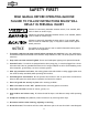
SAFETY FIRST! READ MANUAL BEFORE OPERATING MACHINE FAILURE TO FOLLOW INSTRUCTIONS BELOW WILL RESULT IN PERSONAL INJURY Indicates an imminently hazardous situation which, if not avoided, WILL result in death or serious injury. Indicates a potentially hazardous situation which, if not avoided, COULD result in death or serious injury. Indicates a potentially hazardous situation which, if not avoided, MAY result in minor or moderate injury. It may also be used to alert against unsafe practices.
13. Use correct tool. Do not force machine or attachment to do a job for which it was not designed. 14. Wear proper apparel. Do not wear loose clothing, neck ties, gloves, jewelry, etc. 15. Remove adjusting keys and wrenches before turning the machine on. Make this a habit! 16. Use proper extension cord. When using an extension cord, make sure it is in good condition. Use extension cords 100' or less in length that are rated Hard Service (grade S) or better, and that have a conductor size of 16 A.W.G.
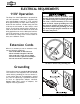
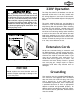
ELECTRICAL REQUIREMENTS 110V Operation This equipment must be grounded. Verify that any existing electrical outlet and circuit you intend to plug into is actually grounded. If it is not, it will be necessary to run a separate 12 A.W.G. copper grounding wire from the outlet to a known ground. Under no circumstances should the grounding pin from any three-pronged plug be removed or serious injury may occur. The Shop Fox® W1673 Bandsaw is prewired for 110 volt operation.
220V Operation The Shop Fox® W1673 16" Bandsaw can also be operated at 220 volts. To do this, consult with the wiring diagram in the back of this manual. Also, you will need a NEMA-style 6L-15A plug and outlet. This equipment must be grounded. Verify that any existing electrical outlet and circuit you intend to plug into is actually grounded. If it is not, it will be necessary to run a separate 12 A.W.G. copper grounding wire from the outlet to a known ground.
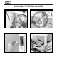
AVOIDING POTENTIAL INJURIES Figure 3. Unplug saw before changing blades. Figure 4. Never start motor with covers open. Figure 5. Remove safety key when not in use. Figure 6. Use push sticks whenever possible.
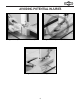
AVOIDING POTENTIAL INJURIES Figure 8. Never place hands in line of cut. Figure 7. Use push blocks when necessary. Figure 9. Use relief cuts for tight curves.
ASSEMBLY INSTRUCTIONS Figure 10. Components laid out for identification. The following is a description of the components shipped with the Shop Fox® W1673 16" Bandsaw. It is recommended that the components be laid out in a similar fashion to those in Figure 10. This will help in identification before beginning assembly. Should any part be missing, examine the packaging carefully to be sure none are among the packing materials. If any key parts are missing, contact Woodstock International, Inc.
Hardware • • • • • • • • • • • • • • • • • • • • • Do not connect the machine to power at this time. The machine must remain unplugged throughout the entire assembly process. Failure to do this may result in serious personal injury. Wear safety glasses during the entire assembly process. Failure to comply may result in serious personal injury.
Bandsaw Body The bandsaw body represents a heavy load. Seek assistance before beginning this step. 1. Seek assistance and place the bandsaw body next to the stand. Rotate the bandsaw body so the access door on the bandsaw body is facing the same way as the cabinet door. Figure 12. Lifting tensioning handle. 2. For safety, remove the bandsaw blade. To do this, open the upper and lower doors on the bandsaw body. Lift the tensioning handle up and carefully remove blade. See Figure 12.
Mounting Motor 1. Make sure the the key is in the keyway on the motor shaft. Align keyway and slide the motor pulley onto the motor shaft as far as it will go. Figure 14. Figure 14. Installing pulley on motor. 2. Align pulley with the hole in the back of the bandsaw body. Slide the motor until mounting holes align with those in top of the stand. Figure 15. 3. Secure the motor with the (4) 5⁄16"-18 x 1" carriage bolts, 5⁄16" hex nuts, lock washers and flat washers provided. 4.
Mounting Table The table is secured to the bandsaw by two trunnions mounted to its bottom surface. These, in turn, have threaded studs that work to lock the table’s angle with respect to the blade. In order to mount the table, you must first mount the trunnion support. Positive Stop Goes Here Secure the trunnion support with the (2) 5⁄16"-18 x 11⁄4" hex bolts and 5⁄16" flat washers as shown in Figure 17.
Fence/Rails The fence is secured to the table with 2 rails. The rails are fastened to the front and back edges of the table with 4 socket head cap screws and spacer sleeves. The fence is most often used between the blade and the bandsaw body upright, so place the rails as shown in Figure 20. To install the rails and fence, follow the instructions below: 1.
ADJUSTMENTS Tensioning Handle Location of Controls On/Off Switch Take the time to familiarize yourself with the controls of your new bandsaw. They will be frequently mentioned throughout the instructions in this manual, and the better you know your machine, the better you can make it perform. Figures 24, 25 and 26 point out the key controls and their locations. Wheel Cover Door Handles DO NOT adjust the bandsaw while it is running.
2300 F.P.M. Speed Changes WHEEL PULLEY The speed diagram on Figure 27 is included to help illustrate belt positions necessary to produce the available speeds. Select the proper speed for the job at hand and move the belts to the desired location. MOTOR PULLEY There are three factors in determining necessary blade speed: the type of blade, the material being cut, and the feed rate at which the material will be cut. Harder wood should be cut at a slower speed with a fine blade.
Install/Remove Blades To remove the blade: DO NOT investigate problems or adjust the bandsaw while it is running. Wait until the machine is turned off, unplugged and all working parts have come to a complete stop before proceeding! 1. Remove the table insert as in Figure 29. 2. Pull out the steel pin at the end of the blade slot in the table. 3. Loosen the guide blocks by turning the thumbscrews counterclockwise and retract the guide blocks away from the blade. 4. Lift the tensioning handle.
Blade Tension Blade tension is one of the most critical factors in the performance of your bandsaw. The blade must be tight enough so it does not sway during a cut, yet stay flexible enough to bend around the wheels. Note: Because of the many factors involved, there is no concrete rule for blade tension. However, there are two common methods for adjustment: Sound and Deflection. To tighten your blade by sound: Many factors determine the ideal tension for every situation.
Tracking Tracking the blade means positioning it on the wheels so it will not come off during operation, thus providing efficient cutting that is effective at the same time. This is usually done by adjusting the tilt of the upper wheel. Blade tracking is one of the most important adjustments you can make for optimal performance of your bandsaw. A properly tracked blade produces very little vibration and heat, and reduces the chance of binding and wandering when cutting. Figure 32. Blade centered on wheel.
Wheel Alignment Wheel alignment is one of the most critical factors for optimal performance from your bandsaw. Heat, vibration, wandering, blade wear, tire wear and overall bandsaw wear are considerably decreased when the wheels are properly aligned or “coplanar.” Coplanar wheels automatically track the blade by balancing it on the crown of the wheel’s tire. This is known as coplanar tracking. To check if your wheels are coplanar: 1.
Wheel Alignment Cont. 6. If the wheels will go parallel but not coplanar, then move the lower wheel at the adjustment hub (Figure 35) as necessary. Top Tilt 7. The adjustment hub allows you to move the lower wheel in the desired direction. Turning all the bolts clockwise in equal amounts pushes the wheel forward. Turning all the bolts counterclockwise brings the wheel backward, closer to the adjustment hub. Used individually, each bolt can control the direction that the wheel tilts. Side Tilt 8.
Blade Guides Rear Support Bearings In order to stabilize the blade during use, it is important that the guide blocks and rear support bearings are monitored and adjusted regularly for optimum blade life and high quality cuts. The rear support bearings keep the blade straight during a cut. They also protect the blade from being pushed too far back. When the blade puts pressure on the bearings, they spin. This reduces friction and blade wear.
Blade Guides Cont. The upper and lower guide blocks reduce side-toside blade wander during cutting. Proper adjustment of these will also minimize heat and increase blade life. To adjust the guide blocks: 1. Find the thumbscrews that allow the guideblock pair to slide back and forth. 2. Set the guide blocks just behind the gullet of the teeth. See Figure 39. This will protect your blade from premature wear because the teeth won’t run against the guide blocks. Figure 39. Guide block position on blade. 3.
Table Adjustments The table can be adjusted 45° to the right or 10° to the left. There is a positive stop bolt (Figure 41) that mounts to the body, under the table. When adjusted correctly, this allows you to bring your table back to square after cutting at an angle. When the positive stop bolt is removed, the table automatically tilts 10° to the left. There is also an adjustable pointer mounted to the trunnion base. This works with the table trunnion gauge to show you the angle of table tilt.
Table Adjustments Cont. It is important to verify that the miter gauge slot is parallel to the blade. This will ensure straight cuts when using your miter gauge and the fence. To make the miter gauge slot parallel with the blade: 1. Install the largest blade you have. Loosen the six trunnion bolts under the table as shown in Figure 44. 2. Place a straightedge next to the blade so it is parallel with the miter gauge slot.
Fence Adjustments Adjustment Bolts There are two knobs on the fence. 1. The long handle to the side of the fence allows you to clamp (turning clockwise) the rear of the fence. See Figure 46. 2. The smaller knob below the rear lock knob is the front knob. This locks (also turning clockwise) the front of the fence in place. Rear Lock Knob 3. When each knob has been loosened (turning counterclockwise), the fence slides back and forth on the rails so you can adjust it to the desired distance from the blade.
Blade Lead DO NOT investigate problems or adjust the bandsaw while it is running. Wait until the machine is turned off, unplugged and all working parts have come to a complete stop before proceeding! An inherent situation with all bandsaws is their tendency to not cut parallel to the fence, even when the fence seems parallel to the blade. Figure 47 demonstrates the effect blade lead can have on your workpiece. This problem is usually caused by three main factors: 1.
OPERATIONS General Always wear safety glasses when operating the bandsaw. Failure to comply may result in serious personal injury. Your Model W1673 Bandsaw will allow you to perform many types of cutting operations. However, the following section is not a complete guide to the many specialized cuts that can be made with this bandsaw; nor does it include the various jigs and aftermarket products that can be used with this bandsaw.
Ripping “Ripping” means cutting along the grain of the wood. This is generally accomplished by using the fence of the bandsaw as a guide to make a straight cut. See Figure 49. Blade selection is important when ripping. Often individual results may vary, but generally, the wider the blade you use, the straighter the cuts.. Also, fewer teeth per inch allow for easier sawdust removal, less heat buildup and more horsepower per tooth.
BLADE WIDTH 1 ⁄4" . . . . 3 ⁄8" . . . . 1 ⁄2" . . . . 5 ⁄8" . . . . 3 ⁄4" . . . . 1" . . . . . 11⁄4" . . . . . . . . . . . . . . . . . . . . . . . . . . . . . . . . . . . . . . . . . . . . . MINIMUM RADII . . . .5⁄8" . . . .13⁄8" . . . .21⁄2" . . . .4" . . . .51⁄2" . . . .75⁄8" . . . .97⁄8" Cutting Curves The ability to cut curves is one of the most useful things a bandsaw can accomplish.
To resaw, follow this basic procedure: Always wear safety glasses when operating the bandsaw. Failure to comply may result in serious personal injury. 1. Ensure that your bandsaw is properly setup according to the Adjustments section in this manual. 2. Use the widest blade that will fit your saw (1"). Also, make sure your blade is sharp and in good condition. 3. Before cutting your workpiece, it is a good idea to test cut a piece of scrap lumber to make sure your bandsaw is set up properly for the job.
Blade Selection Blade Type Blade Width Figure 55 shows three major blade types: Raker, Hook and Skip. Raker (standard) blades usually have many teeth per inch (T.P.I.) and each tooth is flat along the tip. These type of blades leave an excellent finish but cannot clear sawdust very efficiently because of teeth proximity. Skip blades are essentially a raker blade missing every other tooth. These blades clear sawdust efficiently but do not leave as fine of a finish as a raker.
MAINTENANCE General Table And Base Regular periodic maintenance on your Model W1673 Bandsaw will ensure its optimum performance. Make a habit of inspecting your bandsaw each time you use it. Tables can be kept rust-free with regular applications of products like Boeshield® T-9. For long term storage you may want to consider products like Kleen Bore's Rust Guardit™. Check for the following conditions and repair or replace when necessary: 1. Loose mounting bolts. 2. Worn switch. 3.
Maintenance Schedule • Every 2 Hours of Running Time: Clean and lubricate table top, miter slot and fence. • Every 3 Hours of Running Time: Check blade tracking, guide column and table-to-blade. Check gap on guide blocks and thrust bearings. Check blade tension. • Every 5 Hours of Running Time: Oil guide post with light machine oil. • Every 6-8 Hours of Running Time: Replace blades. • Every Year: Replace the rubber V-Belt (recommended).
36
CLOSURE The following pages contain general machine data, parts diagrams/lists and warranty/return information for your Shop Fox® Model W1673 16" Bandsaw. We recommend you keep this manual for complete information regarding Woodstock International, Inc.’s warranty and return policy. If you need additional technical information relating to this machine, or if you need general assistance or replacement parts, please contact the Service Department at 1-360-734-3482 or tech-support@woodstockint.com.
38
39
40
REF PART # 101 102 103 104 105 107 108 109 110 111 112 113 114 115 116 117 118 119 120 122 123 125 126 127 XPB03 XPW07 X167103 X16732104 X1673105 X1673107 X1673108 X1673109 X167310 X1673111 XPRP49M X1673113 X1673114 XPR39M X1673116 X1673117 X1673118 XPR21M XP6202 X1673122 X1673123 X1673125 X1673126 X1673127A X1673127B X1673127C XPS01 X1673129 127A 127B 128 129 DESCRIPTION REF HEX BOLT 5⁄16"-18 X1" FLAT WASHER 5⁄16" SPRING BRACKET BAR SETTING PLATE SPECIAL WASHER BODY SPECIAL NUT SPRING QUICK-HANDLE
REF PART # 159 162 163 164 201 202 203 206 207 211 213 214 215 222 301 302 303 304 305 306 307 308 309 310 311 312 313 314 X1673159 XPSS11 X1673163 XPVA31 XPCB11 XPW02 XPLN03 X1673206 X1673207 XPK34M X1673213 X1673214 XPLW01 X1673222 X1673301 XPB19 XPB05 X1673304 XPTS002 XPW06 XPB51 X1673308 X1673309 XPB66 X1673311 X1673312 XPTS006 X1673314 DESCRIPTION ADAPTER SETSCREW 1⁄4"-20 X 1⁄4" IDLER PULLEY V-BELT A-31 CARRIAGE BOLT 5⁄16"-18 X 1" FLAT WASHER 3⁄8" LOCK NUT 5⁄16"-18 KNOB GUARD KEY 5 X 5 X 20 MOTOR
WARRANTY CARD Name___________________________________________________________________________________________ Street___________________________________________________________________________________________ City ______________________________________________________________State________Zip______________ Phone Number_______________________E-Mail_______________________FAX_____________________________ MODEL # ________________________________________________________________________________________ The followin
FOLD ALONG DOTTED LINE Place Stamp Here WOODSTOCK INTERNATIONAL, INC. P.O.