
Instructions / Assembly

1
INSTRUCTION MANUAL
CHANDELIER FIXTURE
IMPORTANT SAFETY INSTRUCTIONS
INSTALLATION INSTRUCTIONS PERTAINING TO RISK OF FIRE OR INJURY TO PERSONS
1. Read all instructions.
2. Do not install this lighting system in wet locations.
3. CAUTION - When the light is on, the lamp is HOT!
4. CAUTION - Hot surface. Keep away from curtains and other combustible materials.
5. Turn off/unplug and allow to cool before replacing bulb (lamp).
6. All electrical connections must be in accordance with local codes and the National Electrical Code. If
you are unfamiliar with methods of installing electrical wiring, secure the services of a qualified
licensed electrician.
7. This fixture is intended to be mounted to a 4in. square x 2-1/8in. deep metal octagon outlet box. The
box must be directly supported by the building structure.
8. Before starting the installation, disconnect the power by turning off the circuit breaker or by removing
the appropriate fuse at the fuse box. Turning the power off using the light switch is not sufficient to
prevent electrical shock.
SAVE THESE INSTRUCTIONS
TOOLS NEEDED (not included): Ladder, Safety goggles, Gloves, Flathead screwdriver, Phillips screwdriver, Electrical
tape, Wire strippers, Bulb.
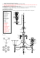
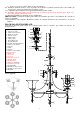
FIXTURE BODY ASSEMBLY INSTRUCTIONS
Refer to the Diagram for reference of the parts
1. Carefully unpack the fixture and lay all of the parts out on a clean surface.
2. Screw the threaded tube into the fixture body coupler and tighten, then place the straigt tube B, fixture
cup, straight tube A separately on to the threaded tube and tighten with the fixture loop.
3. Hang the steel wire to the cleek of fixture body, the other end threaded on the fixture cup hole and
tighten with set screws.
4. Separately hanging the crystal decorative A and crystal decorative B to the corresponding place.
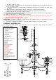
CEILING ASSEMBLY INSTRUCTIONS
1. Make sure the electrical power is off and pull leads down out of junction box.
2. Adjust the length of the chain according to the desired height by removing unnecessary links.
3. Thread the fixture wire and the ground (bare) wire through the chain, feeding it through alternating
links, then through the canopy loop. Loosen the loop ring on the canopy loop and allow ring to slide
down over the chain.
4. Slide the canopy over the canopy loop and the chain (leave ring and canopy loose on chain at this time).
5. Insert and secure the threaded nipple into the canopy loop.
6. Attach the mounting strap to the outlet box using the two outlet box screws provided.
7. Raise the assembled fixture to allow for installation to junction box. Feed the wire and ground wire
through the hole in the center of the mounting strap and rotate the threaded nipple, canopy loop and
preassembled fixture clockwise until the threaded nipple is secure in the mounting strap. Make sure the
fixture cable and ground wires are not twisted during this process.
8. Wrap the ground wire under and around the ground screw which is marked “GND”, and fasten the
ground screw to make sure the ground wire is securely connected.
9. Make the ELECTRICAL CONNECTIONS (Required Supply Circuit: 120V, 60Hz):
a. Connect the neutral wire (with raised ribs and without writing) from the fixture to the neutral (white)
color wire from the Outlet Box.
b. Connect the hot wire (smooth with writing) from the fixture to the hot (black) color wire from the
Outlet Box.
c. Connect the ground (bare) wire from the fixture to the ground wire from the Outlet Box.
d. Secure the connections using the wire connectors. Wrap the wire connections with electrical
tape to secure the connections.
e. Position the wires back inside the outlet box.
10. Slide the canopy back over the canopy loop and tighten to ceiling using the loop ring (Adjust the
ES7730OB4
ES7731OB4