
User manual


well into ultrasonic range (over 120
elements. Besides
-
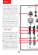
justable CV inputs for modulating pitch
frequency: pitch fm
4
and global fm
5
with their corresponding attenuators.
The main difference between these two is
that pitch fm preserves the shape of the
waveform, while global fm preserves
the overall spectrum, mainly affecting
the frequency of the base tone.
Situated on each side of the pitch con-
trols are two knobs dedicated to com-
ponent mixing. The left knob
6
adjusts
the mix balance between the two ripple
elements (a and b), offering 1:1 pro-
portions in the middle. The correspond-
ing CV input labeled elements mix
7
accepts voltages in the -5V to +5V range,
adding an offset to the manual setting.
The right knob
8
controls the balance
between the fundamental tone and the
ripple elements. There is just the base
tone in its minimum position and just
the elements without the base tone in
the maximum position. The correspond-
ing CV input labeled fund·elem mix
9
accepts voltages in the -5V to +5V range,
adding an offset to the manual setting.
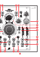
Most of the remaining potentiometers
and jacks correspond to individual rip-
ple elements (a and b) and offer iden-
tical controls over their parameters on
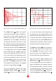
each side of the panel. The red ratio
knobs
10
are relative to the fundamental tone. At
the minimum position, there is no ripple,
just a single parabolic fold squashed by
the decay curve. Increasing the ratio
adds more cycles to the wave, thus shift-
ing the frequency of the corresponding
formant further from the fundamental
frequency. At the maximum position,
about 240 ripples yield a spectral peak 8
octaves above the fundamental frequen-
cy. The two ratio inputs
11
with their
corresponding attenuators
12
facilitate
continuous modulation with external
bipolar control voltages.
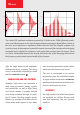
The damp parameters control the decay
rates of the ripples, which are adjusted by
the slider potentiometers near the edges
of the panel
13
and their corresponding
CV inputs
14
, which act as offsets. At the
minimum position, narrow spikes are
generated (about 1% of the fundamental
period), while at the top position, the de-
-
plitude decreases only slightly along the
cycle. note: while these controls behave
-
onant frequency and resonance/ damp-
ing), the actual signal is not obtained
5