
Datasheet
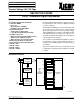

X9C102/103/104/503
5
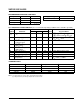
RECOMMENDED OPERATING CONDITIONS
Temperature Min. Max.
Commercial 0°C +70°C
Industrial –40°C +85°C
Military –55°C +125°C
3863 PGM T03.1
Supply Voltage Limits
X9C102/103/104/503 5V ±10%
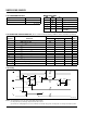
D.C. OPERATING CHARACTERISTICS (Over recommended operating conditions unless otherwise specified.)
Limits
Symbol Parameter Min. Typ.
(4)
Max. Units Test Conditions
I
CC
V
CC
Active Current 1 3 mA CS = V
IL
, U/D = V
IL
or V
IH
and
INC = 0.4V to 2.4V @ max. t
CYC
I
SB
Standby Supply Current 200 500 µA CS = V
CC
– 0.3V, U/D and INC =
V
SS
or V
CC
– 0.3V
I
LI
CS, INC, U/D Input ±10 µAV
IN
= V
SS
to V
CC
Leakage Current
V
IH
CS, INC, U/D Input 2 V
CC
+ 1 V
HIGH Voltage
V
IL
CS, INC, U/D Input –1 0.8 V
LOW Voltage
R
W
Wiper Resistence 40 100 Ω Max. Wiper Current ±1mA
V
H
VH Terminal Voltage –5 +5 V
V
L
VL Terminal Voltage –5 +5 V
C
IN
(5)
CS, INC, U/D Input 10 pF V
CC
= 5V, V
IN
= V
SS
,
Capacitance T
A
= 25°C, f = 1MHz
3863 PGM T05.3
STANDARD PARTS
Part Number Maximum Resistance Wiper Increments Minimum Resistance
X9C102 1KΩ 10.1Ω 40Ω
X9C103 10KΩ 101Ω 40Ω
X9C503 50KΩ 505Ω 40Ω
X9C104 100KΩ 1010Ω 40Ω
3863 PGM T08.1
Notes: (4) Typical values are for T
A
= 25°C and nominal supply voltage.
(5) This parameter is periodically sampled and not 100% tested.
3863 PGM T04.2