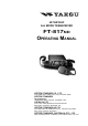
HF/VHF/UHF ALL MODE TRANSCEIVER FT-817ND OPERATING MANUAL VERTEX STANDARD CO., LTD. 4-8-8 Nakameguro, Meguro-Ku, Tokyo 153-8644, Japan VERTEX STANDARD US Headquarters 10900 Walker Street, Cypress, CA 90630, U.S.A. YAESU UK LTD. Unit 12, Sun Valley Business Park, Winnall Close Winchester, Hampshire, SO23 0LB, U.K. VERTEX STANDARD HK LTD. Unit 1306-1308, 13F., Millennium City 2, 378 Kwun Tong Road, Kwun Tong, Kowloon, Hong Kong VERTEX STANDARD (AUSTRALIA) PTY., LTD.
Contents Introduction .................................................... 1 Specifications .................................................. 2 Accessories & Options .................................... 4 Plug Pinout ...................................................... 5 Installation ...................................................... 6 Connecting the Supplied YHA-63 Antenna ......... 6 Connecting the Microphone ................................. 7 Shoulder Strap Installation ..........................
INTRODUCTION The FT-817ND is a compact, innovative multiband, multimode portable transceiver for the amateur radio MF/HF/VHF/UHF bands. Providing coverage of the 160-10 meter bands (include the 60 m band: USA version) plus the 6 m, 2 m, and 70 cm bands, the FT-817ND includes operation on the SSB, CW, AM, FM, and Digital modes, yielding the most comprehensive performance package available for portable operation.
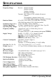
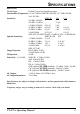
SPECIFICATIONS GENERAL Receive: 100 kHz-30 MHz 50 MHz-54 MHz 76 MHz-154 MHz 420 MHz-470 MHz Transmit: 160-6 Meters (USA: includes 60 meters) 2 Meters 70 Centimeters (Amateur bands only) 5.1675 MHz Alaska Emergency Frequency (USA only) Emission Modes: A1A (CW), A3E (AM), J3E (LSB/USB), F3E (FM), F1D (9600 bps packet), F2D (1200 bps packet) Synthesizer Steps (Min.): 10 Hz (CW/SSB), 100 Hz (AM/FM) Antenna Impedance: 50 Ohms, Unbalanced (Front: Type BNC, Rear: Type M) Operating Temp.
SPECIFICATIONS RECEIVER Circuit Type: Double-Conversion Superheterodyne Intermediate Frequencies:1st: 68.33 MHz (SSB/CW/AM/FM); 10.7 MHz (WFM) 2nd: 455 kHz Sensitivity: SSB/CW AM FM 100 kHz-500 kHz – – – 500 kHz-1.8 MHz – 32 µV – 1.8 MHz-28 MHz 0.25 µV 2 µV – 28 MHz-30 MHz 0.25 µV 2 µV 0.5 µV 50 MHz-54 MHz 0.2 µV 2 µV 0.32 µV 144/430 MHz 0.125 µV – 0.2 µV (IPO, ATT off, SSB/CW/AM = 10 dB S/N, FM = 12 dB SINAD) Squelch Sensitivity: SSB/CW/AM FM 1.8 MHz-28 MHz 2.5 µV – 28 MHz-30 MHz 2.5 µV 0.
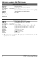
ACCESSORIES & OPTIONS SUPPLIED ACCESSORIES MH-31A8J Hand Microphone FNB-85 Ni-MH Battery Pack (9.6 V, 1400 mAh) NC-72B/C/U or PA-48C/U Battery Charger FBA-28 Battery Case (holds 8 “AA” size Alkaline cells [not supplied]) YHA-63 Whip Antenna for (50/144/430 MHz) E-DC-6 DC Cable Shoulder Strap Ferrite Core Rubber Foot Available Options FNB-85 Ni-MH Battery Pack (9.6 V, 1400 mAh) FNB-72 Ni-Cd Battery Pack (9.6 V, 1000 mAh) NC-72B/C/U or PA-48C/U Battery Charger YF-122S Collins SSB Filter (2.3 kHz/4.
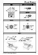
PLUG PINOUT FT-817ND Operating Manual 5
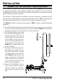
INSTALLATION CONNECTING THE SUPPLIED YHA-63 ANTENNA Your FT-817ND is supplied with a three-section antenna, model YHA-63 which is designed for optimum performance on the 50 MHz, 144 MHz, and 430 MHz. It also works well on the FM broadcast and other VHF bands. This antenna is intended for connection to the front panel’s BNC-type antenna connector.
INSTALLATION CONNECTING THE MICROPHONE To connect the microphone, plug its connector (latch side UP) into the MIC jack on the right side of the transceiver. Press it gently inward until you hear the “click” of the latch. To disconnect the microphone, press gently on the “PUSH ” label on top of the microphone connector’s rubber boot. While pressing on this spot, gently pull the connector outward from the body of the transceiver.
INSTALLATION ALKALINE BATTERY INSTALLATION AND USE The FT-817ND is supplied with the FBA-28 holder for Alkaline “AA” cells. A fresh set of Alkaline cells should provide approximately 5.5 hours of reception under typical conditions. 1. To install or replace the AA cells, first remove the battery cover from the bottom side of the transceiver. Slide the battery cover latch forward, as shown in the illustration, then fold the battery cover upward and set it aside temporarily. 2.
INSTALLATION EXTERNAL POWER CONNECTIONS The FT-817ND may be connected to an external 13.8 Volt DC power source providing at least 3 Amps of continuous-duty current.. The supplied E-DC-6 DC cable may be used for DC connections. While connected to an external DC source, if you have installed the supplied FNB-85 NiMH Battery Pack, the E-DC-6 connection to the external DC power source will allow operation of the FT-817ND while charging of the FNB-85 is in progress.
INSTALLATION FNB-85 NI-MH BATTERY PACK INSTALLATION AND USE The supplied FNB-85 Ni-MH Battery Pack provides 9.6 Volts of DC power for your FT817ND, with a maximum capacity of 1400 mAh. Installation 1. To install the FNB-85 Ni-MH Battery Pack, first remove the battery compartment cover, as described previously. 2. Lift out the FBA-28 battery holder, and disconnect the short cable connected to the FBA-28, as shown in the illustration. 3.
INSTALLATION FNB-85 NI-MH BATTERY PACK INSTALLATION AND USE Charging Charging of the FNB-85 requires the use of either the supplied battery charger (NC-72B/ C or PA-48C/U), or an external 13.8 Volt (±15%) DC source. If the battery charger is used, the FT-817ND must be turned off during charging; if an external 13.8 Volt DC source is used (connected via the supplied E-DC-6 cable), then you may operate the FT-817ND while charging is in progress. 1.
FRONT PANEL CONTROL & SWITCHES PWR Switch Press and hold in the switch for one second to turn to the transceiver on or off. AF Knob The (inner) knob adjusts the receiver audio volume level presented to the internal or external speaker. Clockwise rotation increases the volume level. SQL/RF Knob In the USA version, this (outer) knob adjusts the gain of the receiver’s RF and IF stages.
FRONT PANEL CONTROL & SWITCHES FUNC Keys These three keys select many of the most important operating features of the transceiver. When pressing the key, the current function of that key appears above each of the , , keys (along the bottom of the LCD); rotating the knob scrolls the display through eleven rows of functions available for use via the , , keys. The available features are shown in chart on the next page.
FRONT PANEL CONTROL & SWITCHES Key 1 A/B Press the key to switch between VFO-A and VFO-B on the display. 2 MW key Press and hold in the for 1/2 second to transfer the contents of the VFO into a Memory register. STO Press the key to store the contents of the VFO into the QMB (Quick Memory Bank) register. RPT Press the key to select the direction of the uplink frequency shift (“–,” “+,” or Simplex) during FM repeater operation.
FRONT PANEL CONTROL & SWITCHES Key 8 NB Press the key to activate t h e r e c e i v e r ’s I F N o i s e Blanker. 9 PWR key to select Press the the transmitter power output level (LOW 1, LOW 2, LOW 3, or HIGH). 10 VOX Press the key to enable the VOX (voice-operated transmitter switching system) in the SSB, AM, and FM modes. Press and hold in the key for 1/2 second to recall Menu #51 (for setting the VOX Gain level). CHG Press the key to initiate Battery Charging.
SIDE PANEL SWITCH & CONNECTORS MIC Jack Connect the supplied MH-31A8J Hand Microphone to this jack. SP/PH Jack This 3.5-mm, 2-pin jack provides variable audio output for an external speaker (4 Ω ~ 16 Ω impedance) or earphones. The audio level varies according to the setting of the knob. front panel’s When you insert an earphone plug into this jack, the SP-PH slide switch (located to the right side of this jack) MUST BE set to the “PH” position, to prevent the possibility of injury to your ears.
REAR PANEL CONNECTORS INPUT:13.8V Jack ( ) This is the DC power supply connection for the transceiver, used when operating the transceiver with an external power supply. Use the supplied DC cable to connect this jack to the car battery or base station DC power supply, which must be capable of supplying at least 3A @ 8 ~ 16 VDC. This jack is also used for battery charging (when using the supplied FNB-85 battery pack).
OPERATION Hi! I’m R.F. Radio, and I’m here to guide you through the fine points of the setup and use of your new FT-817ND. I know your anxious to get on the air, but I encourage you to read the “Operation” section of this manual as thoroughly as possible, so you’ll get the most out of this fantastic new rig. Now. . .let’s get operating! TURNING THE TRANSCEIVER ON AND OFF 1. To turn the transceiver on, press and hold in the switch for one second. 2.
OPERATION OPERATING BAND SELECTION This transceiver covers an incredibly wide frequency range, over which a number of different operating modes are used. Therefore, this transceiver’s frequency coverage has been divided into different operating bands, each of with has its own pre-set channel steps and operating modes. You can change the channel steps and operating mode once you get started, of course, per the next section.
OPERATION MENU QUICK START Many aspects of this transceiver’s configuration may be customized using the convenient “Menu” system, which allow you to configure many “set and forget” settings just the way you want to. A full discussion of the Menu system beings on page 58; for now, here is a brief discussion on how to change Menu settings: key for one second to enter the Menu mode. 1. Press and hold in the 2.
OPERATION SETTING THE OPERATING FREQUENCY 1. In the “SSB/CW/DIG” modes, rotate the knob to set the frequency. Clockwise rotation of the knob increases the operating frequency. 2. In the “AM/FM/PKT” modes, rotate the knob to set the frequency. Clockwise rotation of the knob increases the operating frequency. knob to adjust the operating frequency in the “SSB/CW/ 3. You may also use the DIG” modes.
OPERATION OPERATION ON 5 MHZ BAND (U.S. VERSION ONLY) The FT-817ND includes the capability for transmission and reception on the five spot frequencies assigned to the Amateur Service in the United States. To operate on the 5 MHz band: key once to enter the 1. Press the “Memory” mode (a memory channel number “M-nnn” will appear on the display in the space previously occupied by “VFOa” or “VFOb”). 2.
RECEIVER ACCESSORIES CLARIFIER (RECEIVER INCREMENTAL TUNING) The Clarifier (RIT) allows you to set an offset of up to ±9.99 kHz of the receive frequency relative to your transmit frequency. To achieve a wider offset than this, you may use the “Split” operating mode, described later. switch momentarily to activate 1. Press the the Clarifier function. knob, which allows the re2. Turn the ceiver frequency to be varied over a range of 9.99 kHz. 3.
RECEIVER ACCESSORIES IF SHIFT The receiver’s IF SHIFT feature is an effective interference-reduction tool, which allows you to shift the passband response higher or lower without changing the pitch of the incoming signal. switch for one second to acti1. Press the vate the IF SHIFT feature. A “ ”, “ ,” or “ ” icon will appear at the right of the frequency display to indicate the IF SHIFT’s current position. 2. Rotate the knob, as needed, to reduce or eliminate the interference. 3.
RECEIVER ACCESSORIES AGC (AUTOMATIC GAIN CONTROL) The receiver recovery time constant of the AGC system may be modified to match your operating needs. key momentarily, then rotate the knob, as needed, until Operating 1. Press the Function Row 8 [NB, AGC] appears on the display. (AGC) key to toggle the AGC recovery time constant among the follow2.
RECEIVER ACCESSORIES ATT (FRONT END ATTENUATOR) The Attenuator will reduce all signals (and noise) by 10 dB, and it may be used to make reception more pleasant under extremely noisy conditions. This feature is not available on the 144 MHz and 430 MHz. key momentarily, then rotate the knob, as needed, until Operating 1. Press the [ ] Function Row 7 IPO, ATT, NAR appears on the display. (ATT) key to activate the Attenuator. The “ ” icon will appear at the right 2. Press the of the “ATT” indication.
RECEIVER ACCESSORIES AUTOMATIC POWER-OFF FEATURE The APO feature helps conserve battery life by automatically turning the transceiver off after a user-defined period of time within which there has been no dial or key activity. The available selections for the time before power-off are 1 ~ 6 hours, as well as “APO Off.” The default condition for the APO is OFF, and here is the procedure for activating it: key for one second to enter the Menu mode. 1. Press and hold the knob to recall Menu #08 (APO TIME). 2.
TRANSMITTER OPERATION SSB TRANSMISSION Basic Setup/Operation 1. Press the / key so as to select either SSB (LSB/USB) mode. If you are operating on the 7 MHz or lower bands, select the LSB mode. If you are operating on the 14 MHz or higher bands, select the USB mode. 2. Press the key momentarily, then rotate the knob, as needed, until Operating (MTR) key to Function Row 9 [PWR, MTR] appears on the display, then press the select the “ALC” meter function (“alc” will appear at the right side of the “MTR” icon).
TRANSMITTER OPERATION SSB TRANSMISSION VOX Operation The VOX system provides automatic transmit/receive switching based on voice input to the microphone. With the VOX system enabled, you do not need to press the PTT switch in order to transmit. 1. Press the key momentarily, then rotate the knob, as needed, until Operating Function Row 10 [VOX, BK, KYR] appears on the display. (VOX) key to activate the VOX circuitry. The “ ” icon will appear at the 2. Press the right of the “VOX” indication. 3.
TRANSMITTER OPERATION CW TRANSMISSION Operation using Straight Key/External Keying Device When using a straight key, an external electronic keyer, or a computer-generated keying device, please follow the instructions in this section. 1. Insert your key’s (three-conductor) plug into the rear-panel KEY jack. 2. Press the / key, as needed, to select one of the CW (CW/CWR) modes. The “CW” mode utilizes USB-side carrier injection, while the CWR (Reverse) mode utilizes LSB-side injection. 3.
TRANSMITTER OPERATION CW TRANSMISSION 8. You also can adjust the CW sidetone pitch using Menu #20 (CW PITCH). This adjustment also controls the BFO offset (actual pitch of your transmitted signal relative to your current receive frequency). To adjust the CW sidetone pitch: key for one second to enter the Menu mode. Press and hold in the knob to select Menu #20 (CW PITCH). Rotate the knob to select a new pitch tone/BFO offset.
TRANSMITTER OPERATION CW TRANSMISSION Operation using Built-in Electronic Keyer The built-in Electronic Keyer provides a convenient method of generating CW. The Electronic Keyer includes weight and speed adjustments. 1. Connect your keyer paddle’s cable to the KEY jack on the rear panel of the transceiver. 2. Press the / key, as needed, to select the CW (CW/CWR) mode. 3. Press the key momentarily, then rotate the knob, as needed, until Operating Function Row 10 [VOX, BK, KYR] appears on the display.
TRANSMITTER OPERATION FM TRANSMISSION Basic Setup/Operation 1. 2. 3. 4. Press the / key so as to select the FM mode. Press the microphone’s PTT switch, and speak into the microphone in a normal voice. Release the PTT switch to return to the receive mode. If you get reports that your modulation level is too high or too low, you may need to adjust the FM-mode microphone gain.
TRANSMITTER OPERATION FM TRANSMISSION (TON) key to activate the CTCSS tone encoder, which provides a subaudible 4. Press the (TON) key will activate the CTCSS tone repeater access tone. One press of the encoder. In this situation, you will observe the “ ” indicator on the display. If you (TON) key repeatedly, you will observe “ press the ” (CTCSS Encode/Decode), followed by “ ” (Digital Coded Squelch, Encode/Decode). One additional press will disable all repeater-access tone systems.
TRANSMITTER OPERATION FM TRANSMISSION Tone Search Scanning In operating situations where you don’t know the CTCSS tone being used by another station, you can command the radio to listen to the incoming signal and scan in search of the tone being used. To scan for the CTCSS tone in use: 1. Press the key momentarily, then rotate the knob, as needed, until Operating Function Row 12 [TCH, DCH] appears on the display. (TCH) key to activate CTCSS Encoder/Decoder; (the “ ” 2.
TRANSMITTER OPERATION FM TRANSMISSION DCS Operation Another form of tone access control is Digital Code Squelch, or DCS. It is a newer, more advanced tone system that is less susceptible to false triggering than CTCSS. A DCS Encoder/Decoder is built into your transceiver, and operation is very similar to that described above for CTCSS. 1. Set the desired DCS code via Menu #23 (DCS CODE). 2.
TRANSMITTER OPERATION FM TRANSMISSION ARTS TM (AUTO RANGE TRANSPOND SYSTEM) Operation The ARTSTM system uses DCS signaling to inform you when you and another ARTS™-equipped station are within communications range. This can be especially valuable during search-andrescue operations, as a base station can quickly use ARTS™ to alert a field unit that it is out of range; the field unit can then move to a better location to re-establish communications. 1.
TRANSMITTER OPERATION DIGITAL MODE OPERATION (SSB-BASED AFSK) The FT-817ND provides extensive capability for digital mode operation on the HF, VHF, and UHF bands. The use of AFSK (Audio Frequency-Shifted Keying) configurations allows a wide variety of different communication modes to be utilized. The Menu provides for specific digital mode selections, which include custom BFO offsets to optimize the receive and transmit passbands for the mode selected.
TRANSMITTER OPERATION DIGITAL MODE OPERATION (SSB-BASED AFSK) 4. If the optional YF-122C 500 Hz filter has been installed, it may be used for RTTY (NAR) key work. Recall Operating Function Row 7 [IPO, ATT, NAR] then press the to engage the narrow filter. 5. To set up the transmit side, be sure that the Meter is set to monitor ALC voltage. If not, press the key momentarily, then rotate the knob to select to select Operating (MTR) key so as to select metering of Function Row 9 [PWR, MTR], then press the ALC.
TRANSMITTER OPERATION DIGITAL MODE OPERATION (SSB-BASED AFSK) “USER” Defined Digital Modes Also provided in the FT-817ND are two convenient “USER” Digital modes, one each providing USB- and LSB-side injection, which may be used for SSTV, Fax, Pactor, and other digital operating modes. Here is an example involving the configuration of the USER mode for RTTY with USBside injection (as opposed to LSB injection, used in the default “RTTY” mode): 1. Use Menu #26 to set the Digital mode to “USER-U.” 2.
TRANSMITTER OPERATION PACKET (1200/9600 BPS FM) OPERATION The FT-817ND is designed for operation on either 1200 bps or 9600 bps packet, and setup is similar to that described previously for SSB-based modes. A separate Data input adjustment is provided, allowing you to optimize the deviation on the FM Packet modes separately from the SSB-based Digital modes. The RX-Data output lines are fixed-level outputs, not affected by the setting of the AF Gain control. 1.
TRANSMITTER OPERATION AM TRANSMISSION The FT-817ND utilizes low-level amplitude modulation of an early stage for transmission purposes. This capability is primarily provided for emergency use only, as low-power operation typically utilizes more efficient transmission/reception modes. The AM carrier level is preset to 1.5 Watts during alignment at the factory, and should not require further adjustment.
TRANSMITTER OPERATION TIME-OUT TIMER Most often used on FM, the transmitter’s Time-Out Timer (TOT) feature disables the transmitter after a user-defined period of transmission. This feature may be useful in preventing a “stuck microphone” (accidental closure of the PTT switch) from causing interference to other users, and it will also force you to keep your transmission short, thereby conserving battery power. To activate the Time-Out Timer: key for one second to enter the Menu mode. 1.
MEMORY OPERATION QMB CHANNEL QMB Channel Storage 1. Tune in the desired frequency and set the operating mode and bandwidth. If this is an FM channel, set up any required CTCSS/DCS and repeater shift configurations. 2. Press and hold in the key until a double “beep” is heard. The second beep provides audible confirmation that the data has been stored into the QMB memory. (A/B) key momentarily while in Operating Function Row 3 [STO, Pressing the RCL, PMS] will also store a frequency into the QMB register.
MEMORY OPERATION MEMORY OPERATION ON “REGULAR•EMEMORY CHANNELS Normal Memory Storage 1. Tune in the desired frequency, and set the operating mode and bandwidth. If this is an FM channel, set up any required CTCSS/DCS and repeater shift configurations. Standard (default) repeater shifts do not require you to utilize the “split” frequency memory technique, described later. 2. Press the key momentarily, then rotate the knob, as needed, until Operating Function Row 2 [MW, MC, TAG] appears on the display.
MEMORY OPERATION MEMORY OPERATION ON “REGULAR” MEMORY CHANNELS Memory Channel Recall 1. If you currently are in the VFO tuning mode, press the key once to enter the “Memory” mode (a memory channel number “M-nnn” will appear on the display in she space previously occupied by “VFOa” or “VFOb”). 2. To select another memory channel, turn the knob. 3.
MEMORY OPERATION MEMORY OPERATION ON “REGULAR” MEMORY CHANNELS Masking Memory Frequency data stored on a memory channel can be deleted, if desired, from any memory channel except channel “1.” The deletion process is not a “hard” erasure, so if you erase a channel by mistake using this procedure, the memory channel contents can be recovered. 1. Press the key momentarily, then rotate the knob, as needed, until Operating Function Row 2 [MW, MC, TAG] appears on the display.
MEMORY OPERATION MEMORY OPERATION ON “HOME” CHANNEL MEMORIES Four Special one-touch “Home” channels are available, for special frequencies you use often. Either “simplex” or “split” frequency/mode data may be stored in the “Home” channel locations. Special “Home” channels are available for HF (any frequency between 1.8 and 29.7 MHz), 50 MHz, 144 MHz, and 430 MHz.
MEMORY OPERATION LABELING MEMORIES You may wish to append an alpha-numeric “Tag” (label) to a memory or memories, to aid in recollection of the channel’s intended use (such as a club name, etc.). This is easily accomplished using the Menu mode. 1. 2. 3. 4. 5. Recall the memory channel onto which you wish to appended a label. key for one second to enter the Menu mode. Press and hold in the knob to recall Menu #35 (MEM TAG). Rotate the Press the knob to enable the programming of the label.
SPECTRUM SCOPE MONITOR OPERATION The Spectrum Scope Monitor allows viewing of operating activity on 5 channels above and 5 channels below the current operating channel in the VFO mode. When the Spectrum Scope Monitor is activated, the display indicates the relative signal strength on channels immediately adjacent to the current operating frequency.
SMART SEARCH™ OPERATION TM The Smart Search feature automatically stores frequencies where activity is encountered on the current band. When Smart SearchTM is engaged, the transceiver quickly searches above your current frequency, storing active frequencies as it goes (without stopping on them even momentarily). These frequencies are stored in a special Smart SearchTM memory bank, consisting of 50 memories. This feature available on the FM and AM modes.
SCANNING OPERATION This transceiver contains a wide variety of scanning capabilities.
SCANNING OPERATION Scan Skip Programming (Memory Mode Only) Among the memories you have programmed, there may be some stations which you do not wish to scan. For example, broadcast signals (which are transmitted continuously) will cause the scanner to stop, and such channels may be skipped so as to avoid this inconvenience. To remove a channel from the scanning loop: 1. Press the key momentarily, then rotate the knob, as needed, until Operating Function Row 2 [MW, MC, TAG] appears on the display. 2.
SCANNING OPERATION Programmable Memory Scan (PMS) Operation To limit scanning (or tuning) within a particular frequency range, you can use the Programmable Memory Scanning (PMS) feature, which utilizes special-purpose memory pair (“MPL” and “M-PU”). The PMS feature is especially useful in helping you to observe any operating sub-band limits which apply to your Amateur license class. PMS setup is simple to accomplish; 1.
SCANNING OPERATION Note The frequency resolution for these sub-band limits is 100 kHz, although the channel resolution of the sub-band limit memories in whatever you have selected as the current step size. As a result, the frequencies stored in these special memories (M-PL and M-PU) are both rounded down to the nearest 100 kHz for their roles as sub-band limits. Therefore, in the above example, any frequency between 144.300 and 144.399 MHz may be used to store a lower tuning limit of “144.
DUAL WATCH OPERATION Dual Watch is similar, in some respects, to scanning. In Dual Watch, however, the transceiver monitors (squelched) on the VFO-A frequency while periodically checking VFO-B for activity (or vice-versa). A typical example might be for you to set VFO-A to 50.110 MHz, watching for DX stations who might call CQ on that frequency, while periodically checking 28.885 MHz for stations reporting band openings on 6 meters. To activate Dual Watch: 1.
OPERATION ON ALASKA EMERGENCY FREQUENCY: 5167.5 KHZ (U.S. VERSION ONLY) Section 97.401(d) of the regulations governing amateur radio in the United States permit emergency amateur communications on the spot frequency of 5167.5 kHz by stations in (or within 92.6 km of) the state of Alaska. This frequency is only to be used when the immediate safety of human life and/or property are threatened, and is never to be used for routine communications.
MENU OPERATION The Menu System allows you to customize a wide variety of transceiver performance aspects and operating characteristics. Once you have gone through the various Menu customization procedures initially, you will find that you will not have to resort to them frequently during everyday operation. Menu Operation 1. Press and hold in the key for one second. The Menu Item number and a brief title for the Menu Item will appear in the display. 2.
MENU OPERATION 19 20 Menu Item CW PADDLE CW PITCH Function Select the keyer paddle's wiring configuration Setting of the pitch of the CW sidetone, BFO offset, and CW filter center frequencies Set the sending speed for the built-in Electronic keyer 21 CW SPEED 22 23 24 CW WEIGHT DCS CODE DIG DISP 25 DIG MIC 26 DIG MODE 27 DIG SHIFT 28 EMERGENCY 29 30 FM MIC FM STEP 31 32 33 34 35 36 ID LOCK MODE MAIN STEP MEM GROUP MEM TAG MIC KEY 37 38 39 MIC SCAN OP FILTER PKT MIC 40 41 42 43 44 45 46
MENU OPERATION Menu Item 01 [144 ARS] Function: Activate/deactivate the Automatic Repeater Shift when operating on the 144 MHz band. Available Values: OFF/ON Default: ON (depending on transceiver version) Menu Item 02 [430 ARS] Function: Activate/deactivate the Automatic Repeater Shift when operating on the 430 MHz band. Available Values: OFF/ON Default: ON (depending on transceiver version) Menu Item 03 [9600 MIC] Function: Adjust the audio input level from the TNC during 9600 bps Packet operation.
MENU OPERATION Menu Item 09 [ARTS BEEP] Function: Select the ARTS beep mode. Available Values: OFF/RANGE/ALL Default: RANGE OFF: No alert beeps sound; you must look at the display to determine current ARTS status. RANGE: A high tone beep will sound when the transceiver first detects that you are within range, and a low beep will sound when the other station goes out of range.
MENU OPERATION Menu Item 15 [COLOR] Function: Select the illumination color for the LCD illumination. Available Values: COLOR1 (Blue)/COLOR2 (Amber)/COLOR3 (Violet) Default: COLOR1(Blue) Menu Item 16 [CONTRAST] Function: Setting of the display contrast level. Available Values: 1 ~ 12 Default: 5 Menu Item 17 [CW DELAY] Function: Set the receiver recovery time during pseudo-VOX CW semi-break-in operation. Available Values: 10 ~ 500 msec Default: 250 msec The recovery time may be adjusted in steps of 10 msec.
MENU OPERATION Menu Item 21 [CW SPEED] Function: Set the sending speed for the built-in Electronic keyer. Available Values: 4wpm ~ 60 wpm/20cpm ~ 300 cpm Default: 12 wpm (60 cpm) You can set the sending speed according to either of two units of speed (wpm: words per minute; cpm: characters per minute). To switch units between “wpm” and “cpm,” just press the knob. Menu Item 22 [CW WEIGHT] Function: Set the Dot:Dash ratio for the built-in electronic keyer. Available Values: 1:2.5 ~ 1:4.5 Default: 1:3.
MENU OPERATION Menu Item 27 [DIG SHIFT] Function: Define the carrier frequency offset during DIG (USER-L or USER-U) mode operation. Available Values: –3000 ~ +3000 Hz Default: 0 Hz Menu Item 28 [EMERGENCY]: USA Version only Function: Enable Tx/Rx operation on the Alaska Emergency Channel, 5167.5 kHz. Available Values: OFF/ON Default: OFF When this Menu Item is set to “ON,” the spot frequency of 5167.5 kHz will be enabled.
MENU OPERATION Menu Item 32 [LOCK MODE] Function: Select the operation of the front panel’s key. Available Values: DIAL/FREQ/PANEL Default: DIAL DIAL: Locks knob only FREQ: Locks front panel keys and knobs related to frequency control (such as (A/B) key., etc.) and key, PANEL: Locks all front keys and knobs (except key and key) Menu Item 33 [MAIN STEP] Function: Setting of the knob’s tuning speed. Available Values: FINE/COARSE Default: FINE You may choose between two speeds for the knob.
MENU OPERATION Menu Item 36 [MIC KEY] Function: Enable/disable CW keying by the microphone’s [UP]/[DWN] keys. Available Values: OFF/ON Default: OFF When this Menu Item is set to “ON,” press the microphone’s [UP] key to send a “dot,” and press the microphone’s [DWN] key to send a “dash” (while the built-in electronic keyer is engaged). Menu Item 37 [MIC SCAN] Function: Enable/disable scanning access via the microphone’s [UP]/[DWN] keys.
MENU OPERATION Menu Item 43 [SCOPE] Function: Select the Spectrum Scope mode. Available Values: CONT/CHK Default: CONT CONT: The Spectrum Scope sweeps continuously. CHK: The Spectrum Scope sweeps one cycle every 10 seconds. Menu Item 44 [SIDETONE] Function: Adjust the CW sidetone volume level. Available Values: 0 ~ 100 Default: 50 Menu Item 45 [SQL/RF-G] Function: Select the configuration of the front panel’s Available Values: RF-GAIN/SQL Default: Depends on transceiver version knob.
MENU OPERATION Menu Item 51 [VOX GAIN] Function: Set the gain of the VOX circuitry’s input audio detector. Available Values: 1 ~ 100 Default: 50 Menu Item 52 [EXTEND] Function: Enable/disable the extended Menu Items (#53 ~ #57). Available Values: OFF/ON Default: OFF Menu Item 53 [DCS INV] Function: Select “Normal” or “Inverted” DCS coding.
CLONING You can transfer all data stored in one transceiver to another set by utilizing the handy “Cloning” feature. This requires a user-constructed cloning cable which connects the ACC jacks on the two transceivers as shown below. To clone from one transceiver to another, use the following procedure: 1. Insert the Clone Cable into the ACC jack of each transceiver. 2. Turn both transceivers off, then press and hold in the and keys on each radio while turning the power on again.
CAT SYSTEM PROGRAMMING The FT-817ND’s CAT System allows the transceiver to be controlled by a personal computer. This allows multiple control operations to be fully automated as a single mouse click, or it allows a third-party software package (such as contest logging software) to communicate with the FT-817ND without (redundant) operator intervention. The Optional CAT Interface Cable CT-62 is a connection cable for the FT-817ND and your computer.
CAT SYSTEM PROGRAMMING CAT Data Protocol All commands sent from the computer to the transceiver consist of five-byte blocks, with up to 200 ms between each byte. The last byte in each block is the instruction opcode, while the first four bytes of each block are arguments (either parameters for that instruction, or dummy values required to pad the block out to five bytes). Each byte consists of 1 start bit, 8 data bits, no parity bit, and two stop bits.
CAT SYSTEM PROGRAMMING OPCODE COMMAND CHART Command Title Parameter Opcode Notes LOCK ON/OFF CMD PTT ON/OFF CMD Set Frequency P1 P2 P3 P4 01 P1 ~ P4 Frequency Digits 01, 42, 34, 56, [01] = 14.
CAT SYSTEM PROGRAMMING Note 1: CTCSS Tone Note 2: DCS Code CTCSS TONE FREQUENCY (Hz) 67.0 69.3 71.9 74.4 77.0 DCS CODE 79.7 023 025 026 031 032 036 043 047 051 053 82.5 85.4 88.5 91.5 94.8 97.4 054 065 071 072 073 074 114 115 116 122 100.0 103.5 107.2 110.9 114.8 118.8 125 131 132 134 143 145 152 155 156 162 123.0 127.3 131.8 136.5 141.3 146.2 165 172 174 205 212 223 225 226 243 244 151.4 156.7 159.8 162.2 165.5 167.9 245 246 251 252 255 261 263 265 266 271 171.3 173.
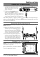
INSTALLATION OF OPTIONAL ACCESSORIES OPTIONAL FILTERS YF-122S/YF-122C/YF-122CN 1. Turn the transceiver’s power off by pressing and holding in the switch for 1/2 second, then remove the FBA-28 Battery Case or FNB-85 Ni-MH Battery Pack from the transceiver. Additionally, disconnect the DC cable from the INPUT: 13.8V jack on the rear panel of the transceiver, when operating the FT-817ND with a DC power supply. 2.
INSTALLATION OF OPTIONAL ACCESSORIES OPTIONAL HIGH-STABILITY REFERENCE OSCILLATOR TCXO-9 The TCXO-9 provides high stability over a wide range of ambient temperatures, so as to enhance digital-mode operating. switch for 1/2 1. Turn the transceiver’s power off by pressing and holding in the second, then remove the FBA-28 Battery Case or FNB-85 Ni-MH Battery Pack from the transceiver. Additionally, disconnect the DC cable from the INPUT: 13.
POWER-ON MICROPROCESSOR RESET PROCEDURE Some or all transceiver settings can be reset to their factory-default states using one of the following power-on routines: + POWER on: Reset all memories and following menu setting to factory-default. Menu #06 (AM STEP), 23 (DCS CODE), 30 (FM STEP), 35 (MEM TAG), 42 (RPT SHIFT), 47 (SSB STEP), and 48 (TONE FREQ). + POWER on: Reset all menu setting (except following menu) to factory-default.
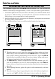
APPENDIX SETUP OF MEMORIES FOR LOW EARTH ORBIT (LEO) FM SATELLITE OPERATION Although the FT-817ND is not capable of “full duplex” operation (simultaneous transmission and reception), its flexible memory system is ideal for configuring a set of memories for LEO satellite work. The example at the right is designed around the popular satellite UO-14, but the same principles apply to operation using AO-27, SO-35, and other such satellites. First, set up a table of the required operating frequencies.
APPENDIX SETUP OF MEMORIES FOR LOW EARTH ORBIT (LEO) FM SATELLITE OPERATION Press the key momentarily, then rotate the knob one click counter-clockwise to (A/B) key to select re-select Operating Function Row 1 [A/B, A=B, SPL]. Press the VFOb (145.970 MHz). Again press the key momentarily, and rotate the knob one click clockwise to re(MW) key momentarily; select Operating Function Row 2 [MW, MC, TAG].
APPENDIX SETUP OF MEMORIES FOR LOW EARTH ORBIT (LEO) FM SATELLITE OPERATION A complete set of frequencies may be stored for each LEO satellite you wish to utilize, and once configured, the FT-817ND provides a flexible and easy-to-use earth station capability for these popular satellites.
APPENDIX BAND DATA FORMAT The FT-817ND BAND DATA Format (available on the ACC jack) is presented below. The BAND DATA line provides a stepped voltage, which denotes the current operating band. This data may be interpreted by an external device (such as an antenna switch or amplifier)to provide automatic band switching. BAND 1.8 MHz 3.5 MHz 7 MHz LEVEL 0.33 V 0.67 V 1.00 V BAND 10 MHz 14 MHz 18 MHz LEVEL 1.33 V 1.67 V 2.00 V BAND 21 MHz 24.5 MHz 28 MHz LEVEL 2.33 V 2.67 V 3.
1. Changes or modifications to this device not expressly approved by VERTEX STANDARD could void the user’s authorization to operate this device. 2. This device complies with part 15 of the FCC Rules. Operation is subject to the following two conditions; (1) This device may not cause harmful interference, and (2) this device must accept any interference including received, interference that may cause undesired operation. 3.
Copyright 2011 VERTEX STANDARD CO., LTD. All rights reserved. No portion of this manual may be reproduced without the permission of VERTEX STANDARD CO., LTD.